


38
TOP
SOFTWARE
UPDATE
PORT
ETHERNET
PORT
FACTORY
RESET
CONNECTS COMMAND
MODULE TO THE
BASE FRAMES
CORNER
POST
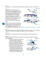
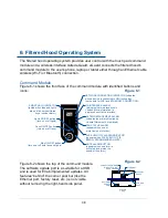
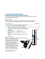
6: Filtered Hood Operating System
The filtered hood operating system provides user control with the touch pad command
module and a wireless interface called eGuard. eG
uard connects the filtered hood’s
command module to the user
’s phone, laptop or tablet either through an Ethernet cable
wireless (Wi-Fi or Bluetooth) connection.
Command Module
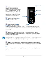
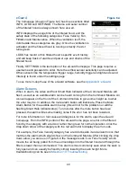
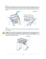
Figure 6-1 shows the front face of the command module with identified buttons and
icons:
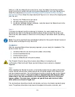
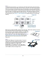
Figure 6-2 shows the top of the command module.
The software update port is a suitable for a USB
and is used for Erlab implemented updates. All
features “behind” the corner post bar (like the
Ethernet port, factory reset, etc.) is not visible
without removing the right-hand side panel.
SMART HALO INDICATOR
(lighted when fans and lights
are on, blinks when filtered
hood is under alarm.)
NETWORK CONNECTION INDICATOR (indicates
when a device is connected to GFH technology
(works both for WIFI and ETHERNET CONNECTION)
MAINTENANCE ALARM
(indicates that maintenances is
needed. More information is
displayed on eGaurd interface).
MUTE ALARM BUTTON
(appears when an alarm is
activated, and mutes the
sound of the alarm.)
Main ON/OFF button
(turn on or off both fans and lights)
Lights ON/OFF button
(turn on or off lights)
Fans ON/OFF button
(turn on or off fans.)
FILTER REPLACEMENT ALARM
(indicates the primary Neutrodine
Unisorb filters must be replaced)
FAN STATUS ALARM
(appears when one or
more fan is out of order)
FACE VELOCITY ALARM INDICATOR
(appears when FACE VELOCITY IS
BELOW RECOMMENDED LIMITS)
Figure 6-1
Figure 6-2
Содержание Protector Airo
Страница 78: ...78 Fans and Lights not working ...
Страница 79: ...79 Vertical sash no longer operates smoothly ...
Страница 80: ...80 Electrical duplex outlets no longer have power Fan operates but lights dim or not working ...
Страница 81: ...81 Contaminates outside the filtered hood ...
Страница 82: ...82 Lights operate but fans will not ...
Страница 83: ...83 Smart Command Alarms ...
Страница 84: ...84 If needed contact Labconco to troubleshoot further ...
Страница 88: ...88 1 2 3 4 5 6 7 8 9 10 13 12 11 14 15 19 22 23 24 26 25 27 28 20 18 REFERENCE SERIAL TAG Figure A 1 ...
Страница 94: ...94 Wiring Diagram Figure C 1 ...
Страница 109: ...109 Figure E 5 TYPICAL NEUTRODINE FILTRATION TECHNOLOGY 12 SCREWS CORNER POST FRONT PANEL HEADER ...


