


66
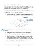
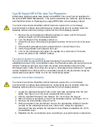
Type C1 Supply HEPA Filter Leak Test Preparation
All biosafety cabinet models were tested to the HEPA Filter Leak Test as described in
the current NSF/ANSI Standard 49. This section describes the methods, specifications,
and Pass/Fail criteria to challenge the supply HEPA filter in the biosafety cabinet.
You never know what a biosafety cabinet has been exposed to, so it is always
recommended to surface decontaminate any components prior to working inside the
biosafety cabinet and/or removing components from the biosafety cabinet.
1. Remove the center work surface by lifting the handles on either end. Pull the
work surface straight out of the biosafety cabinet. Remove the two work surface
wings.
2. Turn the blower of the biosafety cabinet on.
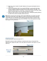
3. Place the aerosol generator on the center drip tray exposed when the center
work surface was removed, see Figure 10-16.
4. Use an extension tube (see Figure 10-16) on the aerosol generator to ensure the
challenge aerosol is delivered to the left most part of the rear baffle. The
challenge must not be delivered to the center portion of the rear baffle (defined
by the center drip tray the generator is resting on).
5. Check the oil level of the aerosol generator is within 1/8 inch (3 mm) of the level
line.
6. If the aerosol generator requires pressurized air, connect the air line.
7.
Verify the generator’s air pressure is 23 psi.
8. Turn on the photometer and allow it to operate for a minimum of 5 minutes.
Leave the valve in the “CLEAR” setting.
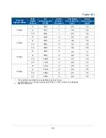
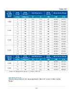
Theoretical Upstream Concentration
If you do not wish to connect the Upstream Sampling Tube to the photometer to
establish the actual 100% concentration value, the theoretical value will need to be used
instead. Testing at Labconco has shown the actual concentration varies from the
theoretical value. Table 10-4 shows the actual vs. calculated concentrations for Type C1
models. Establish the 100% and 0% concentration levels for the photometer using the
actual values provided in Table 10-4 for the model being tested.
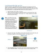
Upstream Concentration Sampling
You never know what a biosafety cabinet has been exposed to, so it is always
recommended to surface decontaminate any components prior to working inside the
biosafety cabinet and/or removing components from the biosafety cabinet.
1. Locate the Upstream Sample Tube on the right side, protruding from the rear
baffle. See Figure 10-17. On some models this tube is clear.
2. Pull the Upstream Sample Tube forward. Do not remove the cap yet.
3. When prompted by the photometer, turn on the appropriate number of Laskin
nozzles on the aerosol generator (see Table 10-4), uncap the Upstream
Содержание Logic+ A2
Страница 148: ...148 Wiring Diagrams The wiring diagram is also located on the blower plenum cover behind the dress panel 100 115V...
Страница 149: ...149 208 240V...
Страница 151: ...151 Blower only will not start...
Страница 152: ...152 Lights only will not illuminate...
Страница 153: ...153 UV Light will not illuminate...
Страница 154: ...154 Airflow Alert activating...
Страница 155: ...155 Filter Life Gauge not at 100 when new...
Страница 156: ...156 Contamination in the work area...
Страница 200: ...200 Figure 23 4 1 2 4 3 5 7 6 8 8...
Страница 201: ...201 END OF 3849920 Figure 23 5 9 10 11 12 13...


