Page 4
LAARS HEATING SYSTEMS
B o ile r
S pace H eating -
R efer to D ocum ent 108 0
Ta n k
Figure 3. Piping Schematic.
Cold
Water
Supply
Hot
Water
Supply
M in i-C o m b o
Ta n k
C o ld W ate r
In let
S h u t O ff
Va lve
E x pa n s io n
Ta n k
U n io n
C h ec k Va lve
o r
B a ck-F lo w
P reve nte r
Figure 4. Typical Expansion Tank Installation.
Figure 2. Dimensional Information.
Dimensions inches
mm
Size
A
50
14
356
75
15
381
100
16
406
125
17
432
Boiler In/Out NPT
(all sizes)
1¼
Gas NPT (all sizes)
½*
Domestic Hot Water (all sizes)
Inlet/Outlet NPT
¾
Minimum clearances from
combustible surfaces:
Left Side: 2"
51mm
Right Side: 2"
51mm
Rear: 2"
51mm
Front: 4"
102mm Top: 23" 584mm
Service clearances:
Allow 4"
102mm on each side
for piping access.
*¾" for model 125 Natural.
60
(1521)
28
(711)
41.5
(1054)
32.5
(826)
7
(178)
24
(610)
24
(610)
.75
(19)
62.5
(1588)
Domestic
Hot Water
Outlet
Cold Water
Inlet
Side View
Front View
Check Valve
Tank
Pump
Boiler Flue Collar 4 (102)
Dimensions shown
in inches (mm).
7
(178)
24
(610)
Tank
Aquastat
Drain
Valve
Tank
Relief
Valve
Содержание MCH
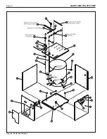
Страница 8: ...Page 8 LAARS HEATING SYSTEMS Figure 8 Parts Identification...
Страница 10: ...Page 10 LAARS HEATING SYSTEMS...
Страница 11: ...Mini Combo id Page 11...


