background image

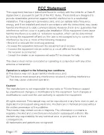
This equipment has been tested and found to comply with the limits for a Class B 

digital device, pursuant to part 15 of the FCC Rules. These limits are designed to 

provide reasonable protection against harmful interference in a residential 

installation. This equipment generates, uses, and can radiate radio frequency 

energy, and if not installed and used in accordance with the instructions, may cause 

harmful interference to radio communications. However, there is no guarantee that 

interference will not occur in a particular installation. If this equipment does cause 

harmful interference to radio or  television reception, which can be determined 

by turning the equipment off and on, the user is encouraged to try to correct the 

interference by one or more of the following measures: 

• Reorient or relocate the receiving antenna.

• Increase the separation between the equipment and receiver. 

• Connect the equipment into an outlet on a circuit different from that to which 

   the receiver is connected. 

• Consult the dealer or an experienced radio/TV technician for help. 

This device must not be co-located or operating in conjunction with any other 

antenna or transmitter. 

Operation is subject to the following two conditions: 

(1) This device may not cause harmful interference, and 

(2) This device must accept any interference received, including interference 

     that may cause undesired operation.

Caution! 

The manufacturer is not responsible for any radio or TV interference caused 

by unauthorized changes or modifications to this equipment. Such changes or 

modifications could void the user authority to operate the equipment.

All rights reserved. This manual may not be reproduced in any form, even in part, or 

duplicated or processed using electronic, mechanical or chemical process without 

the written permission of the publisher.

This booklet may contain errors or misprints. The information it contains is 

regularly checked and corrections are included in subsequent editions. We 

disclaim any responsibility for any technical error or printing error, or their 

consequences.

All trademarks and patents are recognized.

FCC Statement

Page | 11       

 www.lacrossetechnology.com/support 

           BBB86088 

Содержание BBB86088

Страница 1: ...Model BBB86088 Instruction Manual DC 103017 Atomic Digital Wall Clock with Indoor Outdoor Temperature...

Страница 2: ...tomic Time WWVB Signal Time Alarm Activate Deactivate Alarm Snooze Sensor Reception and Search Temperature Trend Arrows Position TX141 Bv2 Sensor Low Battery Let s Get Social Care and Maintenance Warr...

Страница 3: ...sensor transmits The TX button lets you manually transmit a signal LED TX Button 2 Insert 2 AA batteries into your clock 3 Configure basic settings 4 After 5 minutes place your sensor outside in a sha...

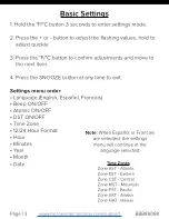
Страница 4: ...mode 2 Press the or button to adjust the flashing values hold to adjust quickly 3 Press the F C button to confirm adjustments and move to the next item 4 Press the SNOOZE button at any time to exit Se...

Страница 5: ...Page 4 Language Beep ON OFF Atomic ON OFF DST ON OFF Time Zone 12 24 Hour Format DST Hour Minutes Year Month Date AM Fahrenheit Celsius Press and release the F C button to select Fahrenheit or Celsiu...

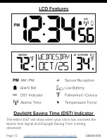
Страница 6: ...eception Low Battery Fahrenheit Celsius Temperature Trend Daylight Saving Time DST Indicator The letters DST will show when your clock has received the atomic time signal and Daylight Saving Time is b...

Страница 7: ...e solid when connected Hold the MINUS button for 3 seconds to manually search for the WWVB atomic time signal For information about WWVB visit http bit ly AtomicTime Time Alarm 1 Hold the ALARM button...

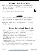
Страница 8: ...m for 24 hours Snooze Sensor Reception Search If the signal is lost your clock will display the LAST DATA recorded from the sensor for 10 minutes After that 10 minutes if the signal does not come back...

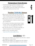
Страница 9: ...s or floors Be sure the sensor is mounted vertically to allow moisture to drain out properly Watch sensor mounting video http bit ly TH_SensorMounting The trend arrows indicate changes in your tempera...

Страница 10: ...attery contacts and also those of the device prior to battery installation Ensure the batteries are installed with correct polarity and Remove batteries from equipment when it is not to be used for an...

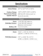
Страница 11: ...val 32 F to 122 F 0 C to 50 C 40 F to 140 F 40 C to 60 C 300 feet 91 meters open air Every 51 seconds Clock TX141 Bv2 Sensor 2 AA LR6 IEC batteries 2 AA LR6 IEC batteries Batteries not included Batter...

Страница 12: ...connected Consult the dealer or an experienced radio TV technician for help This device must not be co located or operating in conjunction with any other antenna or transmitter Operation is subject to...

Отзывы: