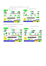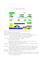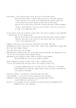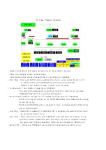
6. CHECK POINTS BEFORE PRODUCTION
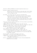
1. Power "ON" by main Breaker and Welder Breaker.
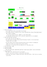
2. Power "ON" by main Power Switch on Control Panel and Power on PLC Control
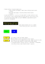
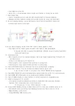
3. Push POWER ON button, and check Water Pump Motor is turning on.
- If water pump motor is out of order, cooling water can not circulate through
welding transformer, welding controller, electrode plate which will occur
high temperature to damage parts.
- If water temperature is higher than ambient temperature, turn on Cooling Fan.
Cooling Fan should be running on Summer season
- WATER TEMPERATURE CONTROLLER is set up 45˚C (113 F). If water temperature
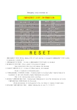
is over 45˚C (113 F) 45, machine is stop and WATER TEMPERATURE HIGH (on
EMERGENCY STOP INFORMATION of Touch Panel) is lit.
※ During winter time, antifreeze should be mixed up with cooling water,
and avoid contamination of water, and refill the water after evaporation.
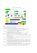
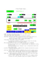
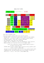
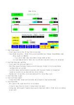
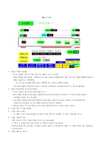
4. Select PIPE type.
5. Select Size to make cage.
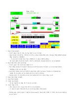
- Set up dimension is smaller than actual size, expand diameter by BELL EXPAND.
- Pole is forward automatically, so do not need to push POLE F/W button.
6. Push POLE F/W button until 5mm gap of back cylinder, and set up Pole Position same
value showing in Green Color bar (left).
※ When you set up value for Pole Position, Barrel Size and Bell Size, RESET
button should be pressed and entered.
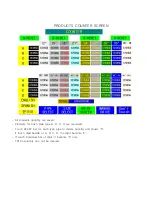
7. Set up all other dimension as per actual size to produce.
8. Adjust air pressure of air cylinder.
- Normally 3 bar for 4mm (0.157") longitudinal wire x 5mm (0.195") spiral wire.
- High pressure of air cylinder is helpful for good welding, but make parts faster
worn out and overload to Drum Motor.
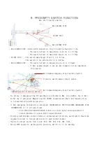
9. Welding signal Proximity Switch is attached on back drum side.
- Welding point and Proximity Switch position should be closed for good welding.
10. All sliding and moving parts should be lubricated by Dry Lubricant(Graphite) or
light engine oil. Grease should be used on bearings only.
- Grease mixed with cement dust will be became abrasive materials.
- Check all bolts and nuts fastened tight.
- Check welding parts to be isolated each other.
Содержание KN-1248-G3
Страница 3: ......
Страница 4: ......
Страница 5: ......
Страница 6: ......
Страница 54: ......
Страница 55: ......
Страница 57: ......
Страница 61: ......
Страница 62: ......
Страница 63: ......
Страница 64: ......
Страница 65: ......
Страница 66: ......
Страница 67: ......
Страница 68: ......
Страница 69: ......
Страница 71: ......
Страница 73: ......
Страница 75: ......
Страница 77: ......
Страница 78: ......
Страница 79: ......
Страница 80: ......
Страница 81: ......
Страница 82: ......
Страница 90: ...MANUAL OF WIRE CUTTING MACHINE MODEL KN 2CT ...
Страница 107: ......
Страница 108: ......
Страница 109: ......
Страница 110: ......
Страница 111: ......
Страница 112: ......
Страница 113: ......
Страница 123: ... 10 NO PART NUMBER PART NAME QT Y 1 WIRE COVER 1 2 WIRE GUIDE RACK 4 3 CT 06 08 TABLE PLATE 1 4 CT 06 09 BEARING 6212 1 ...

