background image

Содержание inferno DX 4WD

Страница 1: ...AVEL FOR TOP HANDLING ON ROUGH TRACKS FULLY INDEPENDENT SUSPENSION WITH OIL FILLED SHOCKS INCLUDES NEW LIGHTWEIGHT ALUMINUM CHASSIS NEWLY DESIGNED GEARBOXES COME ASSEMBLED AND ALLOW EASY ACCESS AND MAINTENANCE FEATURES INDIVIDUAL FRONT AND REAR BRAKING SYSTEMS 21 2 Cycle Buggy Muffler Ai Cleaner Radio 2 Channel with Heavy Duty Servos Misc Electric Starter Glow Driver 2 Cycle Model Fuel ...

Страница 2: ...actual size enabling you to place a screw directly on the picture to ensure you have selected the appropriate size Feel free to cut off this page to have beside you when building the kit Quantity Used Type of Screw In This Step Size of Screw M3 x10 SfT Screw 21 t FINDING THE CORRECT SCREWS AND WASHERS IN THIS KIT All nuts and bolts used throughout this kit are metric size Therefore some of the not...

Страница 3: ...knife removed to trim the o Not INCORRECT ffash oN enough removed 8 Trial fit all parts to ensure proper fit before attaching them permanently 9 Do not use excessive force when tightening self tapping type screws into plastic Overtightening will cause the threaded portion of the plastic to strip It is recommended to stop tightening when some resistance is felt after the threaded portion enters the...

Страница 4: ...eiver battery switch harness and make sur the transmitter is turned off Make sure all batteries are disconnected alld 011 fuel drained 3 Send written instructions which include a list of all items returned a THOROUGH explanation ofthe problem and the service needed and your phone number where you can be reached during the day Ifyou expect your repair to be covered under warranty be sure to include...

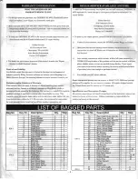
Страница 5: ...uminum Collar 2 12 105 Differential Case Parts 3 56 Torque Rod Pivot 1 13 106 Differential Joint 4 57 Front Bumper 1 14 107 Spur Gear 1 58 Radio Plate 1 16 108 Center Diff Joint Lono 1 59 Front Support Plate 17 109 Center Dill Joint Short 1 I 1 60 8mm Aluminum Collar 2 17 no 8mm x 16mm Bearino 2 61 2mm Stopper 18 Assembled 28 8mm x 16mrn Bushino 8 6 62 Linkage Guide 2 17 18 111 Front Bulkhead A 1 ...

Страница 6: ...own Cap on and secure it with the Shock Ring while without making any swishing to remove any trapped air remaining allowing the excess oil to overflow out of the shock noise If the shock doesn t operate inside properly repeat the first two steps Diaphragm e kR Shock Cap Tighten the Shock Ring tight enough so that the oil will not leak out Note When ordeling replacement shocks you must purchase the...

Страница 7: ...x 20 H IHScrew 3mm x 44mm 21 Suspension Shaft STEP 2 E olipIE I _____ Install the left side the Use this hole for the same as the right M3x20 H H Screw Suspension Shaft E clip E 2 5 Assemble two Upper Anns f H Rear Upper Susp Arm 8 INSTALLATION OF LOWER REAR SUSPENSION ARMS 20 M3 x 3 Set Screw 4 x 77mm Susp Shaft Bushing M4 x 12Set Screw Install the M4x12 Set Screw so that it protrudes 3mm out the...

Страница 8: ...ched to the the point the set screw Shaff Torque Rod Pivot in step 13 will touch This will hold the shafts more securely TORQUE ROD ASSEMBLY Assemble one Torque rod Install the 6 8mm Ball in the side of the Ball End with the l 8 1 41 5 42mm 1 Install the 6 8mm Ball Ends so the rod is 41 5mm to 42mm long Cd tI INSTALLATION OF SUSPENSION 4 S Suspension Plate B PLATE B 1m M3 x 30 3 washer M3 Flanged ...

Страница 9: ...m x 16mm Bushing Eoclip Eo 2 5 Front Susp Arm M4 x 12 Set Screw Assemble both sides Hub Carrier L Knuckle Arm L 5 M4x18 SIT Screw Install the M4x64 Suspension Shaft r before installing the M4x18 Str Screwo 3mm Install the M4x12 Set Screw so that it protrudes 3mm out the bottom of the Suspension Arm To ensure that you don t mFRONT SHOCK Shock Bushing INSTALLATION Front Shock lose the 3 x 27mm Susp ...

Страница 10: ...Screws W 25S 3 10 1 rtl 0 r _ 10 H IHSo 4 3 10 i c SO 110 op C C 0 JI1 jrj M3x10HlH lJines _ __ mENGINE INSTALLATION Ones it may M4 x10 Screws 4 Mounting Plates M4 x 10 Screws M4 x 8Screw_________ _ For some eng1 to enlarge be necessary 10 ...

Страница 11: ...p Eo7 i Servo Saver Horn 8 ServoSaver Horn C Servo Saver Sp nng M3 x 15 Serew Tapered Washer purple M3 x 15 sere Center Rod Steering TO Asse bl Ie Rod m e two Tie Rods j 68 mm Ball Tie Rod CAj jl S P to pivot R a io Plate Post M3x10srrs erew 11 ...

Страница 12: ... 8S 129 Front Dill 3 8S 1 09 2O BS 13 l3Q 85 57 BSW 40 DBS l05 I I I from l J I g r O r j g II f v d O 8S 77 1 Ir n 6 1 O 1Y BS 43 1 1 1 1383 8S 127 85 13 BS 78 1 t EF 39 EXPLODED VIEW l8 100 ...

Страница 13: ... BS 124 BSW 6 I I I I BS 114 j J BS l02 from 1382 BSW 40 BS l05 BS 55 BS l09 101 Rear Dill I I ll an i lBS l0l j ifromO ...

Страница 14: ...Screw rn Note The Muffler and Air Cleaner are sold separately All O S engines corne with an air cleaner T L M3 10srr Screw L __ __ 1 s o Make a slight I bend in the tube Long I as shown below _ Rubber Bushing Aluminum Tube bending diagram C _ Actual size U p Mounting hole diagram Muffler Wire o o Fuel Tank 14 ...

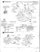
Страница 15: ...Y Use a hole that is 16mm from the center Trim off M3 x 10 SIT Screw the shaded area jj1 Front Support Plate J r C 8mm Aluminum Collar It I I M3 x 3 Set Screw I Linkage Guide Use the center hole Adjust the Steering Rod so that the center line of the servo arm and the servo saver are parallel Hold the Linkage Guide with a hex wrench when tightening the M3 Nylon Nut Tighten completely then loosen 1 ...

Страница 16: ...ply pressure to the brake pads 1mREAR MOUNT ASSEMBLY 2mm Stopper 1t 2mm Washer Stopper High Throttle High Throttle should allow the carbo to fully open Be sure that the throttle linkage rod doE S not bend because of too much servo throw If this happens move the Linkage Guide one hole in on the Servo Arm Qlllllllllll M3 Nut NOTE If installing an O S 21RX B you will need to purchase the BS 114 Linka...

Страница 17: ...o the grooves flITIRE INSTALLATION REAR Wide 19 Wheel Boll M3Nuls Wheel Bolt FRONT Narrow _ k I 8x 16 x 1 5mm Washer m TRIMMING THE BODY Engine Hole Trim out the shaded areas as ShOW R Drill or cut the needed holes Antenna Hole Drive Washer 2 6mmPin shaded area l i fW These spet ially desi ed scissol s make trimming bodies a bl eeze The sander comes in handy for finishing the rough edges KYOR1000 ...

Страница 18: ...e You may also choose to spray the body by masking off different color areas with masking tape Be sure to always apply the darkest colors first m MOUNTING THE BODY AND WING Body Pins _ Bend the Body Pins up at V the ends This will allow you to install and remove them easier At this time add the decals to the body as shown on the Box lid or however you prefer lliJ illJ e H 6 I T Micro Line Tape is ...

Страница 19: ...l and squeeze the from entering the engine button Make sure that the engine clean the filter with soap starts in the proper direction and water every 3 4 tanks Counter Clockwise of fuel Then saturate the filter with oil Muffler should face the gTound Inferno OX Hop Ups Now that you have tried the Inferno DX and are hooked on gas cars its time to hop up the Inferno DX and go racing The following is...

Страница 20: ...l A mbly SS 121 I ss n I M4x4 Set Screw i I SS 39 ll SS 77 _SS 5_2_ _ SS 1 0 _ 6 _ _ I M3x10 SIT Screw I J 0 SS 36 lBS lll M4Washer l1li Center Diff e u lBS 37 0 Front Rear Diffs 0 0 SS 107 1 M4 Washer M3x12 SIT Screw I 1 lSS 77 Servo Saver w l c l Rear Shock 2U02 Center Dill 20 ...

Страница 21: ...ning the Inferno DX 6 Always check the engine glow plug to make sure it is 12 When tuning your engine be careful not to lean out the working properly prior to starting You can easily check carburetor needle valve too much This will cause the it by hooking it up while out ofthe engine If it glows engine to overheat To monitor the temperature lightly bright it is probably okay Also check the coil ca...

Страница 22: ...xl KYOC6368 BSW 06 Wing Stay 878889 90xl 92x291x4 KYOC6245 BSW 40 Pin Spike Tire 132x2 KYOC2570 FM 029 Body Pin 10 pcs KYOC4725 FM 073 Pilot Shaft 79xl KYOC4307 FM 185 Joint 123x2 KYOC4360 KC 07 King Pin 42x4 KYOC6000 KC 18 3mm Stopper 23x10 KYOC2990 KC 45 Special Clutch Shoes 81 xl 80x2 I II Stock KYO Description Contents KYOC2955 SO 54 Clutch Bell 13T 85xl KYOC6020 EF 039 Strap L 76x6 KYOC2915 L...

Страница 23: ...lll1l1 ll lllimm 3 x 44mm Susp Shaft 2 Torque Rod Pivot 1 E ring E 2 5 B fa Q O1r tO E ring E 3 4 INSTALLATION OF LOWER REAR SUSP ARMS M3 x 3 Set Screw 2 IlIll 3 x 27mm Susp Shaft 0 0 lEI INSTALLATION OF FRONT ASSEMBLY 2 M4x 12 Set Screw 2 IIIIIIIIIIIIIIIIIII IIIIII M3 x 15 SiT Screw 1 ill11111111 1 1 3 x 44mm Susp Shaft 2 E ring E 2 5 4 01 to M4 x 20 SiT Screw 2 1 3mm Stopper 2 E ring E 3 4 M3 x ...

Страница 24: ...y Mount Metric Ruler o 10 20 30 4r 50 60 70 80 90 KY0Z7502 24 1 1 1 1 1 1 11 1 I Ill CONTROL RODS i M3x3 Set Screw 6 M3 Nylon Nut 1 M2 Washer 2 2mm Stopper 6 G Linkage Guide 1 Brake Rod 2 c lJ Il REAR MOUNli ASSEMBLY M3 x 15 Screw 8 Olllllilililililillilllllillill llililim M3 Nut 4 PLASTIC PARTS GUIDE The shaded parts are not used Wing Joint 2 I I m TIRE INSTALLATION 2 6 x 16mm Pin 4 JI O ring Lar...

Отзывы: