Kyocera PF-520 Скачать руководство пользователя страница 1

SERVICE

MANUAL

Published in September 2010

3M9SM061

Rev. 1

PF-520
PF-530

All manuals and user guides at all-guides.com

all-guides.com

Содержание PF-520

Страница 1: ...SERVICE MANUAL Published in September 2010 3M9SM061 Rev 1 PF 520 PF 530 All manuals and user guides at all guides com a l l g u i d e s c o m...

Страница 2: ...your area for proper disposal ATTENTION IL Y A UN RISQUE D EXPLOSION SI LA BATTERIE EST REMPLACEE PAR UN MODELE DE TYPE INCORRECT METTRE AU REBUT LES BATTERIES UTILISEES SELON LES INSTRUCTIONS DONNEES...

Страница 3: ...Revision history Revision Date Replaced pages Remarks 1 September 17 2010 1 1 1 1 2 4 1 3 1 to 1 3 14 All manuals and user guides at all guides com...

Страница 4: ...This page is intentionally left blank All manuals and user guides at all guides com...

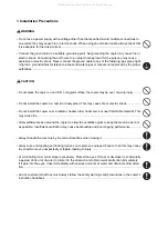
Страница 5: ...fety of their customers their machines as well as themselves during maintenance activities Service personnel are advised to read this booklet carefully to familiarize themselves with the warnings and...

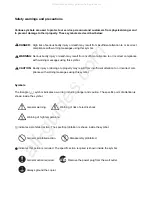
Страница 6: ...r damage to property may result from insufficient attention to or incorrect com pliance with warning messages using this symbol Symbols The triangle symbol indicates a warning including danger and cau...

Страница 7: ...y cause fire or electric shock Do not install the copier near a radiator heater other heat source or near flammable material This may cause fire Allow sufficient space around the copier to allow the v...

Страница 8: ...that the copier is correctly connected to an outlet with a ground connection Check that the power cable covering is free of damage Check that the power plug is dust free If it is dirty clean it to rem...

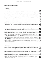
Страница 9: ...ng screws Check that all the caution labels that should be present on the machine according to the instruction handbook are clean and not peeling Replace with new ones if necessary Handle greases and...

Страница 10: ...This page is intentionally left blank All manuals and user guides at all guides com...

Страница 11: ...hanical problems 1 3 12 1 4 Assembly and disassembly 1 4 1 Precautions for assembly and disassembly 1 4 1 1 Precautions 1 4 1 1 4 2 Paper feed section 1 4 2 1 Detaching and refitting the retard roller...

Страница 12: ...3M9 3NA 2 3 Operation of the PWBs 2 3 1 PF main PWB 2 3 1 2 3 2 PF heater PWB 2 3 4 2 4 Appendixes 2 4 1 Appendixes 2 4 1 1 Wiring diagram 2 4 1 All manuals and user guides at all guides com...

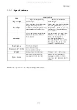
Страница 13: ...gh Quality and Custom 1 to 8 Paper size A4 A5 B5 ISO B5 Letter Legal Statement Executive Oficio II Folio Custom A4 A5 B5 ISO B5 Letter Legal Statement Executive Oficio II Folio 16k Envelope 10 Envelop...

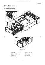
Страница 14: ...al Figure 1 1 1 9 8 7 5 5 6 2 4 1 3 7 1 Cassette 2 Paper size dial window 3 Paper size dial 4 Paper gauge 5 Paper width guides 6 Paper length guide 7 Positioning pins 8 Interface connector 9 PF rear c...

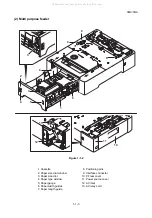
Страница 15: ...1 Cassette 2 Paper size dial window 3 Paper size dial 4 Paper type window 5 Paper gauge 6 Paper width guides 7 Paper length guide 8 Positioning pins 9 Interface connector 10 PF rear cover 11 Power sou...

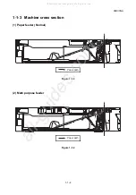
Страница 16: ...9 3NA 1 1 4 1 1 3 Machine cross section 1 Paper feeder Normal Figure 1 1 3 2 Multi purpose feeder Figure 1 1 4 Paper path Paper path All manuals and user guides at all guides com a l l g u i d e s c o...

Страница 17: ...ature and low humidity an abrupt change in the environmental temperature and cool or hot direct air Avoid places subject to dust and vibrations Choose a surface capable of supporting the weight of the...

Страница 18: ...e Installation Guide for installation 1 2 7 8 4 3 5 6 1 2 7 8 4 3 5 6 9 9 1 Paper feeder 2 Outer case 3 Plastic bag 600 x 800 4 Left pad 5 Right pad 6 Plastic bag 120 x 250 7 Left sub cursor 8 Right s...

Страница 19: ...tapes Procedure 1 Remove the tapes Paper feeder Normal two tapes Multi purpose feeder four tapes Figure 1 2 2 Tape Paper feeder Normal Multi purpose feeder Tape Tape Tape Tape Tape All manuals and us...

Страница 20: ...cursors Multi purpose feeder only Procedure 1 Attach the right and left sub cursors to the cassette Figure 1 2 3 Right sub cursor Left sub cursor Left sub cursor Cassette Right sub cursor All manuals...

Страница 21: ...s printing and displays the paper misfeed mes sage on the operation panel To remove paper misfed in the machine open the PF rear cover Figure 1 3 1 Paper misfeed indication MFP Figure 1 3 2 Paper misf...

Страница 22: ...5 Sensors Registration sensor MP feed sensor Eject sensor PF feed sensor 1 PF feed sensor 2 1 2 3 4 5 Paper jam location Cassette 1 MP tray Machine inside Fuser Eject sections Duplex section Cassette...

Страница 23: ...MP feed sensor Eject sensor PF feed sensor 1 PF feed sensor 2 PF feed sensor 3 1 2 3 4 5 6 Paper jam location Cassette 1 MP tray Machine inside Fuser Eject sections Duplex section Cassette 2 Cassette...

Страница 24: ...does not turn on during paper feed from paper feeder 2 F 1404 PF feed sensor 1 does not turn ON PF feed sensor 1 PFFS1 does not turn on during paper feed from paper feeder 3 F 1413 PF feed sensor 1 do...

Страница 25: ...rom paper feeder 1 C 4203 The eject sensor ES does not turn on during paper feed from paper feeder 2 C 4204 The eject sensor ES does not turn on during paper feed from paper feeder 3 C 4212 Eject sens...

Страница 26: ...nel An error message consists of a message prompting a contact to service personnel and a four digit error code indicating the type of the error Figure 1 3 5 Self diagnostic indication MFP Figure 1 3...

Страница 27: ...the bushes and gears Check for broken gears and replace if any Defective PF lift motor Replace the PF lift motor Defective PF main PWB Replace the PF main PWB see page 1 4 6 1030 PF lift motor error...

Страница 28: ...lift motor Replace the PF lift motor Defective PF main PWB Replace the PF main PWB see page 1 4 6 1500 PF heater 1 high tempera ture error paper feeder 1 A temperature higher than 75 C 167 F is detect...

Страница 29: ...tive PF main PWB Replace the PF main PWB see page 1 4 6 1540 PF heater 1 high tempera ture error paper feeder 3 A temperature higher than 75 C 167 F is detected Defective connec tor cable or poor cont...

Страница 30: ...e the PF heater PWB or PF main PWB see page 1 4 8 1 4 6 1610 PF heater 2 low temperature error paper feeder 1 An external temperature higher than 5 C 9 F is not detected when one minute elapses after...

Страница 31: ...ter PWB or PF main PWB see page 1 4 8 1 4 6 1630 PF heater 2 low temperature error paper feeder 2 An external temperature higher than 5 C 9 F is not detected when one minute elapses after PF heater 2...

Страница 32: ...e the PF heater PWB or PF main PWB see page 1 4 8 1 4 6 1650 PF heater 2 low temperature error paper feeder 3 An external temperature higher than 5 C 9 F is not detected when one minute elapses after...

Страница 33: ...PWB YC6 Defective drive transmission sys tem of the PF paper feed motor Check if the rollers and gears rotate smoothly If not grease the bushes and gears Check for broken gears and replace if any Def...

Страница 34: ...le If none replace the cable PF paper feed motor and PF main PWB YC6 Defective drive transmission sys tem of the PF paper feed motor Check if the rollers and gears rotate smoothly If not grease the bu...

Страница 35: ...the cord 8 Defective PWB Replace the PF heater PWB or PF main PWB see page 1 4 8 1 4 6 2 PF paper feed clutch does not operate 1 Defective connector cable or poor con tact in the connector Reinsert th...

Страница 36: ...n see page 1 4 6 6 A paper jam in paper feeder is indicated when the main power switch is turned on 1 A piece of paper torn from paper is caught around PF paper feed sensor Check visually and remove i...

Страница 37: ...ssette installed incorrectly Check the paper width guide visually and remedy or replace if necessary 3 Multiple sheets of paper are fed Check if the paper is excessively curled Change the paper Paper...

Страница 38: ...3M9 3NA 1 3 18 This page is intentionally left blank All manuals and user guides at all guides com...

Страница 39: ...relay cord refer to the figure below When handling PWBs printed wiring boards do not touch parts with bare hands The PWBs are susceptible to static charge Do not touch any PWB containing ICs with bare...

Страница 40: ...PF rear cover 2 Release two hooks and then remove the retard guide and retard spring Figure 1 4 2 3 Level the retard roller unit and then remove it Figure 1 4 3 PF rear cover Retard guide Retard sprin...

Страница 41: ...fitting the retard roller unit firmly install the retard spring onto the projec tion of the retard roller unit Figure 1 4 4 Protrusion Retard guide Retard spring Retard roller unit Retard guide Retard...

Страница 42: ...paper feed roller unit Procedure 1 Remove the cassette 2 Remove the retard roller unit see page 1 4 2 Figure 1 4 5 3 Turn the paper feeder with the bottom side up Figure 1 4 6 Cassette Paper feeder Al...

Страница 43: ...the lever B and then remove the paper feed roller unit and pickup spring 6 Check or replace the paper feed roller unit and refit all the removed parts Figure 1 4 7 Lever A Pickup spring Paper feed ro...

Страница 44: ...r 4 Remove the actuator and spring Figure 1 4 8 5 Remove all connectors from PF main PWB Multi purpose feeder Fourteen Paper feeder Normal Ten Figure 1 4 9 Hook Top cover Actuator Spring Hook PF main...

Страница 45: ...3M9 3NA 1 4 7 6 Remove the screw 7 Release four hooks and then remove the PF main PWB Figure 1 4 10 PF main PWB Screw Hook Hook Hook Hook All manuals and user guides at all guides com...

Страница 46: ...tte 2 Remove two screws 3 Insert a flat blade screwdriver into the cutout and release two hooks Figure 1 4 11 4 Turn the paper feeder with the bottom side up 5 Release two hooks and then remove the fa...

Страница 47: ...from PF heater PWB Figure 1 4 13 7 Remove the screw 8 Release two hooks and then remove the PF heater PWB Figure 1 4 14 YC4 YC2 YC1 YC3 TB1 TB2 TB3 PF heater PWB PF heater PWB Screw Hook Hook All man...

Страница 48: ...ter PWB 3 Remove the connector of the PF fan motor 1 4 Remove the connector of the PF therm istor 1 Figure 1 4 15 5 Release two hooks and then remove the top heater unit Figure 1 4 16 YC4 YC2 YC3 TB1...

Страница 49: ...age 1 4 10 2 Release two hooks and then remove the top cover 3 Remove the actuator and spring Figure 1 4 17 4 Remove YC2 TB1 YC14 YC111 and YC115 connectors from the PF main PWB Figure 1 4 18 Hook Top...

Страница 50: ...up 6 Remove four screws Figure 1 4 19 7 Turn the paper feeder with the bottom side up 8 Release two hooks of the drive section from the inside of the paper feeder Figure 1 4 20 Screw Screw Screw Screw...

Страница 51: ...paper feeder with the top side up and remove the top frame unit Figure 1 4 21 10 Remove the side heater unit Figure 1 4 22 Top frame unit Side heater unit All manuals and user guides at all guides co...

Страница 52: ...3M9 3NA 1 4 14 This page is intentionally left blank All manuals and user guides at all guides com...

Страница 53: ...9 1 Paper feed roller 2 Pickup roller 3 Retard roller 4 Middle roller 5 Middle idle pulley 6 Paper feed holder 7 PF lift sensor PFLS 8 Retard guide 9 Retard holder 10 Cassette base 11 Bottom plate 12...

Страница 54: ...rm air blowing section Figure 2 1 4 Warm air blowing section block diagram 1 2 3 4 5 6 Top heater unit Side heater unit Exhaust Intalke 1 PF fan motor 1 PFFM1 2 PF heater 1 PFH1 3 PF thermistor 1 PFTH...

Страница 55: ...n the cas sette 5 PF feed sensor PFFS Detects a paper misfeed in the paper feeder 6 PF cassette size switch PFCSSW Detects the paper size dial setting 7 PF rear cover switch PFRCSW Breaks the safety c...

Страница 56: ...s opened 8 PF paper feed motor PFPFM Drives the paper feed mechanism 9 PF lift motor PFLM Operates the bottom plate in the cassette 10 PF paper feed clutch PFPFCL Controls the drive of the paper feed...

Страница 57: ...main PWB Figure 2 3 1 PF main PWB silk screen diagram 1 4 1 7 1 4 1 4 1 7 3 1 2 1 12 1 9 1 3 1 C E C E C E 3 1 2 1 5 1 2 1 YC2 YC6 YC9 YC111 YC10 YC4 YC7 YC3 YC5 YC1 PH3 PH2 PH1 YC115 YC114 YC113 YC1...

Страница 58: ...OPSEL0 I 0 3 3 V DC Paper feeder selection signal 9 OPSEL1 I 0 3 3 V DC Paper feeder selection signal 10 OPSEL2 I 0 3 3 V DC Paper feeder selection signal 11 PAPSIZE O 0 3 3 V DC PFCSSW On Off 12 24V...

Страница 59: ...ce YC14 1 COV_SW O 0 3 3 V DC PFRCSW On Off Connected to PF rear cover switch 2 GND O Ground YC111 1 24V O 24 V DC 24 V DC power source Connected to PF fan motor 1 and 2 2 FAN1 O 0 24 V DC PFFM1 On Of...

Страница 60: ...3M9 3NA 2 3 4 2 3 2 PF heater PWB Figure 2 3 2 PF heater PWB silk screen diagram 1 2 1 4 1 3 5 1 YC4 YC2 YC1 YC3 TB1 TB2 TB3 All manuals and user guides at all guides com...

Страница 61: ...1 On Off YC2 1 LIVE O 120 V AC 220 240 V AC AC power output Connected to PF heater 2 2 N C Not used 3 N C Not used 4 NEUTRAL O 120 V AC 0 V 220 240 V AC 0 V PFH2 On Off YC3 1 3 3V I 3 3 V DC 3 3 V DC...

Страница 62: ...3M9 3NA 2 3 6 This page is intentionally left blank All manuals and user guides at all guides com...

Страница 63: ...3 4 5 6 7 8 9 9 8 7 6 5 4 3 2 1 1 2 3 4 5 6 7 8 9 10 11 12 12 11 10 9 8 7 6 5 4 3 2 1 GND OPSCLK OPRDYN OPSDI OPSDO 3 3V GND OPSEL0 OPSEL1 OPSEL2 PAPSIZE 24V TRANSCLN 24V FEEDCLN 24V 1 2 3 4 4 3 2 1...

Страница 64: ...3M9 3NA 2 4 2 This page is intentionally left blank All manuals and user guides at all guides com...

Страница 65: ...All manuals and user guides at all guides com...

Страница 66: ...All manuals and user guides at all guides com a l l g u i d e s c o m...

Отзывы: