background image

2FT

1-6-18

Yes

No

Start

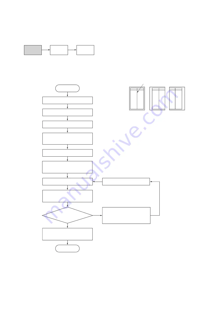
Enter maintenance mode.

Enter “034” using the numeric keys.

Press the start key.

Press the interrupt key.

Press the start key 

to output a test pattern.

Is the image correct?

Press the start key.

The new setting is stored.

Press the stop/clear key to exit 

maintenance mode.

End

Select the “ADJ. LSU OUT TIMING” 

using the up/down cursor keys.

For output example 1, decrease 
the value using the left cursor key.
For output example 2, increase 
the value using the right cursor key.

Press the start key.

Select the items to be adjusted 

using the up/down cursor keys.

Setting range (Initial setting)
LSU OUT: –7.0 – +10.0 (–1.0)
LSU BYP: –7.0 – +10.0 (0.4)
LSU T1: –7.0 – +10.0 (–1.2)
LSU DUP: –7.0 – +10.0 (0.3)
Changing the value by 1 moves the 
center line by 0.1 mm.

LSU OUT: Drawer
LSU BYP: Bypass tray
LSU T1: Ffirst paper feeder
LSU T2: Optional second paper feeder
LSU T3: Optional third paper feeder
LSU DUP: Duplex copying (second face)

 (10-3) Adjusting the center line of image printing

Make the following adjustment if there is a regular error between the center lines of the copy image and original when
paper is fed from the drawer.

Caution:

Check the copy image after the adjustment. If the image is still incorrect, perform the above adjustments in maintenance
mode.

Procedure

Figure 1-6-33

U034

U067

(P. 1-6-36)

U072

(P. 1-4-18)

Center line of printing

Correct image

Output 

example 1

Output 

example 2

Содержание KM-2550

Страница 1: ...SERVICE MANUAL Published in June 2005 842FT112 Version 3 0 KM 2550...

Страница 2: ...sion if battery is incorrectly replaced Replace only with the same or equivalent type recommended by the manufacturer Dispose of used batteries according to the manufacturer s instructions CAUTION Dou...

Страница 3: ...marks 3 0 14 June 2005 1 1 1 1 1 2 1 3 6 1 3 13 1 4 2 1 4 3 1 4 4 1 4 13 1 4 25 1 5 36 1 6 11 1 6 16 1 6 21 1 6 25 1 6 38 1 6 41 1 6 43 1 6 44 1 6 50 2 1 9 2 1 10 2 1 11 2 2 1 2 2 2 2 2 3 2 3 10 2 3 1...

Страница 4: ...This page is intentionally left blank...

Страница 5: ...sonnel to ensure the safety of their customers their machines as well as themselves during maintenance activities Service personnel are advised to read this booklet carefully to familiarize themselves...

Страница 6: ...this symbol CAUTION Bodily injury or damage to property may result from insufficient attention to or incorrect compliance with warning messages using this symbol Symbols The triangle symbol indicates...

Страница 7: ...or dusty place This may cause fire or electric shock Do not install the copier near a radiator heater other heat source or near flammable material This may cause fire Allow sufficient space around the...

Страница 8: ...carefully Always check that the copier is correctly connected to an outlet with a ground connection Check that the power cable covering is free of damage Check that the power plug is dust free If it i...

Страница 9: ...trapped wire and missing screws Check that all the caution labels that should be present on the machine according to the instruction handbook are clean and not peeling Replace with new ones if necess...

Страница 10: ...This page is intentionally left blank...

Страница 11: ...3 11 Installing the scan system option 1 3 43 1 3 12 Installing the hard disk option 1 3 45 1 4 Maintenance Mode 1 4 1 Maintenance mode 1 4 1 1 Executing a maintenance item 1 4 1 2 Maintenance modes...

Страница 12: ...3 The bypass paper feed solenoid does not operate 1 5 36 14 The drawer paper feed clutch doesnot operate 1 5 36 15 The cleaning lamp does not turn on 1 5 36 16 The exposure lampdoes not turn on 1 5 36...

Страница 13: ...ner wires 1 6 25 3 Detaching and refitting the ISU reference 1 6 28 4 Detaching and refitting the laser scanner unit 1 6 29 5 Adjusting the longitudinal squareness reference 1 6 32 6 Adjusting magnifi...

Страница 14: ...ons 2 1 17 2 1 8 Duplex section 2 1 18 1 Paper conveying operation in duplex copying 2 1 19 2 2 Electrical Parts Layout 2 2 1 Electrical parts layout 2 2 1 1 PCBs 2 2 1 2 Switches and sensors 2 2 2 3...

Страница 15: ...sleep mode 20 s Paper feed system Automatic feed Capacity Drawers 300 sheets 80 g m2 100 sheets 90 105 g m2 Manual feed Capacity Bypass 50 sheets A4 11 x 8 1 2 or less 25 sheets A3 B4 11 x 17 8 1 2 x...

Страница 16: ...ator key counter fax system network scanner hard disk additional memory and original cover Printer functions Printing speed Same as copying speed First print time Approx 4 9 s A4 11 x 8 1 2 Resolution...

Страница 17: ...dle 9 Bypass tray 10 Support guide 11 Slider 12 Contact glass 13 Original size indicator plates 14 Left cover 15 Waste toner box 16 Toner container release lever 17 Toner container 18 Cleaner rod 19 F...

Страница 18: ...dicator 14 Sort key and indicator 15 Staple key and indicator 16 Program key 17 Zoom key Left cursor key 18 Auto 100 key Down cursor key 19 Original Size key Up cursor key 20 Paper Select key Right cu...

Страница 19: ...ion Figure 1 1 3 Machine cross section Light path Paper path 1 Paper feed section 2 Optical section 3 Drum section 4 Developing section 5 Transfer and separation section 6 Fixing section 7 Exit and sw...

Страница 20: ...r 25 7 Gear 25 8 Gear 20 9 Paper feed clutch gear 10 Gear 30 11 Gear 31 12 Gear 25 13 Gear 49 14 Gear 30 23 15 Developing gear 25 16 Developing gear 26 17 Gear 40 18 Fixing joint gear 29 19 Gear 31 20...

Страница 21: ...ture between 20 C 4 F and 55 C 131 F and at a relative humidity not higher than 90 RH Avoid abrupt changes in temperature and humidity Avoid exposure to any substance which is harmful to or may affect...

Страница 22: ...n Choose a surface capable of supporting the weight of the machine Place the machine on a level surface maximum allowance inclination 1 Avoid air borne substances that may adversely affect the machine...

Страница 23: ...tional original cover or DP Connect the connector of the drawer heater Connect the power cord Load paper Make test copies Output an own status report maintenance item U000 Exit maintenance mode Start...

Страница 24: ...ter case 5 Lower left pad 6 Lower right pad 7 Upper left pad 8 Upper right pad 9 Inner frame 10 Left spacer 11 Rear spacer 12 Rear pad 13 Skid 14 Belt 15 Eject sheet 16 Machine cover 17 Bar code label...

Страница 25: ...er as necessary see pages 1 3 7 to 1 3 8 1 Remove the fifteen tapes Figure 1 3 2 2 Remove the two pins for light source unit Figure 1 3 3 Install the optional paper feeder Remove the tapes and pins Ta...

Страница 26: ...tainer release lever and gently push the toner container into the MFP Push the container all the way into the MFP until it locks in place 5 Restore the toner container release lever 6 Close the front...

Страница 27: ...e if the toner container contains toner and to see if the toner container sensor malfunctions and then try again 6 Press the stop clear key 1 Load paper in the drawer 1 Enter 000 using the numeric key...

Страница 28: ...eration at toner empty detection SINGLE MODE U260 Changing the copy count timing After ejection U264 Setting the display order of the date Month Day Year Inch specifications Day Month Year Metric spec...

Страница 29: ...paper feeder by aligning the positioning insertion sections of the first paper feeder with the positioning pins at the rear part of the second paper feeder Two paper feeders can be added Figure 1 3 6...

Страница 30: ...steps 2 and 3 until an adequate image is obtained Figure 1 3 8 Adjusting the center line 1 Run maintenance mode 034 Select ADJ LSU OUT TIMING and press the start key First optional cassette Select LS...

Страница 31: ...r frame Figure 1 3 10 3 Place the DP on the MFP by fitting the pins into the holes at the hinge sections of the DP and sliding them toward the front side Figure 1 3 11 4 Secure the DP with the two TP...

Страница 32: ...Prepare an original on which 4 lines are drawn 15 mm from the edges and the center line is drawn 2 Set the original on the DP and make a test copy to check the copy image At this time set the paper g...

Страница 33: ...rter A larger value makes the image longer Figure 1 3 16 Maintenance mode 071 leading edge timing adjustment 1 Run maintenance mode 071 Select LEAD1 For adjustment of the back side in duplex copying s...

Страница 34: ...nterrupt key Make a test copy to check the image If an adequate image cannot be obtained carry out the following adjustment 2 For copy example a increase the value For copy example b decrease the valu...

Страница 35: ...move the stopper from the front side 5 Open the left cover until it is put horizontally Figure 1 3 19 6 Turn the wire guide section of the duplex unit in the direction indicated by the arrow Figure 1...

Страница 36: ...ure 1 3 22 1 9 Hang the hook of the plate lock on the con veying unit and then turn the plate lock to fit the hole to the claw of the duplex unit Figure 1 3 22 2 10 Secure the duplex unit with the two...

Страница 37: ...10 0 Changing the value by one moves the lead ing edge by 0 1 mm 3 Output the test pattern again 4 Repeat steps 2 and 3 until an adequate image is obtained Figure 1 3 25 Adjusting the center line 1 Ru...

Страница 38: ...N 120 V specifications 2C960030 220 240 V specifications 2C960040 One 1 M4 x 10 tap tight S binding screw P N B3024100 Procedure 1 Remove the main body from the paper feeder see page 1 6 7 2 Remove t...

Страница 39: ...Pass the connector of the cassette heater through the hole located in the right frame of the machine to pull it out 2 Insert the projections at the rear side of the cassette heater mounting plate int...

Страница 40: ...ove of the frame and put it inside the power source PCB Fit the wire into the groove so that the band mounted to the wire is located above the frame Figure 1 3 29 7 Reattach the power source PCB to it...

Страница 41: ...1 M3 bronze nut P N C2303000 Key counter mounting plate P N 2C960100 Key counter wire P N 2C960110 Procedure 1 Fit the key counter socket assembly to the key counter retainer using the two screws and...

Страница 42: ...re as shown in the illustra tion 6 Fold the 7 pin connector of the key counter wire back pass the wire through the clamp at the upper part of the controller box and hang it Figure 1 3 32 7 Pass the co...

Страница 43: ...12 Insert the key counter into the key counter socket assembly 13 Turn the power switch on and enter the maintenance mode 14 Run maintenance item U204 and select KEY COUNTER 15 Exit the maintenance m...

Страница 44: ...the staple mounting plate may be deformed resulting in a malfunction Figure 1 3 35 Be sure to remove the tape for the intermediate tray at Procedure 16 not removing before mount ing Figure 1 3 36 Proc...

Страница 45: ...sing a small screw driver or the like and remove the front side cover Figure 1 3 39 5 Remove the screw and the fitting part located on the right side and then remove the left front cover 6 Open the fr...

Страница 46: ...e the three screws and then remove the ejection cover and inner ejection cover Figure 1 3 41 8 Remove the two screws and then remove the cover Figure 1 3 42 Screws Screw Ejection cover Inner ejection...

Страница 47: ...e transfer unit closer to the ejection side and then secure the front side using the TP bind screw M3 x 06 and the rear side using the pin Figure 1 3 43 Release the lever securing fitting 11 Loosen th...

Страница 48: ...ook holder onto the screw and then retighten the screw Figure 1 3 45 14 Insert the intermediate tray from the front side of the MFP while pushing the hook to the back and then push the pin located at...

Страница 49: ...the connector of the transfer unit 18 Connect the 13 pin connector of the inter mediate tray to YC5 on the engine circuit board Figure 1 3 48 Attach the covers 19 Attach the cover that has been remove...

Страница 50: ...e cover as it is fitted to the staple unit from the ejection side and then secure it using the TP bind screw M3 x 06 24 Attach the inner cover that has been removed by Procedure 3 to its original posi...

Страница 51: ...1 3 52 27 Open the staple cover and then insert the staple cartridge into the staple unit 28 Close the staple cover Figure 1 3 53 Operation check 1 Insert the MFP power plug into an outlet and then tu...

Страница 52: ...er Figure 1 3 54 3 Release the fitting parts using a small screw driver or the like and remove the front side cover Figure 1 3 55 4 Remove the screw and the fitting part located on the right side and...

Страница 53: ...e the three screws and then remove the ejection cover and inner ejection cover Figure 1 3 57 6 Remove the two screws and then remove the cover Figure 1 3 58 Screws Screw Ejection cover Inner ejection...

Страница 54: ...pped hole with the large pin and the rear side with the small pin Figure 1 3 59 9 Loosen the screw that secures the drive unit located at the rear side of the job separator to make it ready for starti...

Страница 55: ...e located inside of MFP while pushing the copy tray to the back along the groove Figure 1 3 61 Attach the left front cover JS 13 Pull out the connector of the job separator from the hole of the left f...

Страница 56: ...this time take care that the routed wire in the groove does not come off 16 Attach the inner cover that has been removed by Procedure 2 to its original posi tion 17 Close the front cover Figure 1 3 64...

Страница 57: ...ositioned to the projection of the memory slot on the fax con trol PCB assembly 1 4 Push the free end of the module down toward the board 2 5 Attach the mounting plate and the ground wire that have be...

Страница 58: ...Attach the fax control PCB assembly 9 Loosen the screw on the printer board 10 While taking care that the mounting surface of the board does not contact the frame sec tion of the rear cover insert the...

Страница 59: ...ear cover Figure 1 3 70 Attach the NCU PCB assembly 14 Connect the NCU wire connector on the NCU PCB assembly to the YC2 connector on the fax control PCB assembly Figure 1 3 71 15 Secure the NCU PCB a...

Страница 60: ...to the shield box and then attach it with the six screws and TP tap tight screw M4 x 6 to its original position Figure 1 3 74 Connect the telephone line to the line terminal 18 Insert the modular conn...

Страница 61: ...n Figure 1 3 76 20 Lift the two pawls and remove the operation section sheet cover Figure 1 3 77 21 Remove the operation section sheet and replace it with the operation section sheet for fax of the co...

Страница 62: ...so that it sticks fast to the surface while matching the top surface to the top left corner and firmly pressing the whole area down as shown in the illustration 25 Push all the one touch keys to chec...

Страница 63: ...one touch sheet 29 Divide the one touch sheet of the corre sponding language into two parts and then mount them on the one touch securing sheet each Bring back the left cover of the operation section...

Страница 64: ...el and do not use the PRS TUV WXZ and OPER labels Figure 1 3 84 Attach the certification label 120 V specifications only 31 Adhere the FCC68 label onto the shield cover after wiping the cover with alc...

Страница 65: ...the cover Figure 1 3 86 Install the scanner board 3 Insert the scanner board into the OPT1 opening of the shield box and firmly push the CN5 connector on the scanner board all the way into the YC12 c...

Страница 66: ...by Procedure 1 into the shield box and refit it to its original position using the six screws a If the fax system is installed refit the shield cover using the six screws a and screw b to its origina...

Страница 67: ...ht back and then remove the cover 2 Insert the hard disk in the socket on the printer board PCB 3 Refit the cover which is removed with step 1 4 Turn the power switch on and initialize the hard disk a...

Страница 68: ...c keys Enter 001 using the up down cursor keys or numeric keys and press the start key Enter the maintenance item number using the up down cursor keys or numeric keys The selected maintenance item is...

Страница 69: ...sting the amount of slack in the paper 10 15 15 20 20 5 U053 Performing fine adjustment of the motor speed 0 3 0 0 6 0 5 0 1 0 1 0 2 1 3 1 5 0 6 U055 Setting the motor periodic drive 1 30 U059 Setting...

Страница 70: ...of sheets for fixing control thick paper 152 170 180 190 5 30 U162 Stabilizing fixing forcibly U163 Resetting the fixing problem data U167 Checking the fixing counts U199 Checking the fixing temperat...

Страница 71: ...twork scanner U504 Initializing the scanner NIC U506 Setting the time out 10 Others U901 Checking clearing copy counts by paper feed locations U903 Checking clearing the paper jam counts U904 Checking...

Страница 72: ...output is complete the screen for selecting an item is displayed Completion Press the stop clear key at the screen for selecting an item The screen for selecting a maintenance item No is displayed U0...

Страница 73: ...keys shown below as required 2 Press the start key The phone number is set and the screen for selecting a maintenance item No is displayed Completion To exit this maintenance item without changing th...

Страница 74: ...rmed when set to 999 in duplex copy mode continuous copying is performed regardless of the setting Copy density Keys on the operation panel other than the energy saver preheat key 5 To control the pap...

Страница 75: ...ey The screen for selecting a maintenance item No is displayed U021 Initializing memories Description Initializes the setting data other than that for adjustments due to variations between respective...

Страница 76: ...Completion Press the stop clear key The screen for selecting a maintenance item No is displayed U026 Evacuation of backup data Description Transfers the backup data of the main PCB to the EEPROM Purpo...

Страница 77: ...cription Drives each motor Purpose To check the operation of each motor Method 1 Press the start key The screen for selecting an item is displayed 2 Select the motor to be operated using the up down c...

Страница 78: ...on of each clutch Method 1 Press the start key The screen for selecting an item is displayed 2 Select the clutch to be operated using the up down cursor keys 3 Press the start key The clutch turns on...

Страница 79: ...s the start key The screen for setting is displayed Setting 1 Select the item to be set using the up down cursor keys The selected item is displayed in reverse 2 Change the setting using the left righ...

Страница 80: ...t an A3 11 x 17 VTC pattern in interrupt copy mode 2 Measure A and B on the VTC pattern Figure 1 4 1 and perform the following adjustments if they are different from the correct sizes A Drive motor sp...

Страница 81: ...the start key The value is set Interrupt copy mode While this maintenance item is being performed copying from an original can be made in interrupt copy mode 1 Press the interrupt key The machine ente...

Страница 82: ...the screen for setting The screen for selecting a maintenance item No is dis played U065 Adjusting the scanner magnification Adjustment See pages 1 6 33 and 34 U066 Adjusting the leading edge registr...

Страница 83: ...the image longer and decreasing it makes the image shorter 3 Press the start key The value is set Interrupt copy mode While this maintenance item is being performed copying from an original can be ma...

Страница 84: ...l can be made in interrupt copy mode 1 Press the interrupt key The machine enters the interrupt copy mode 2 Set the original and press the strat key To return to the screen for setting press the inter...

Страница 85: ...s maintenance item is being performed copying from an original can be made in interrupt copy mode 1 Press the interrupt key The machine enters the interrupt copy mode 2 Set the original and press the...

Страница 86: ...ss and when scanning an original from the DP Method Press the start key Setting 1 Change the setting using the left right cursor keys Increasing the setting makes the luminosity higher and decreasing...

Страница 87: ...tment starts When adjustment is complete each adjusted value is dis played If a problem occurs during auto adjustment DATA XX XX is replaced by an error code is displayed and operation stops Should th...

Страница 88: ...scanning position on the slit glass when the DP is used Setting 1 Press the start key The screen for selecting an item is displayed 2 Select ON or OFF using the up down cursor keys The selected item i...

Страница 89: ...preset values and press the start key to register the setting 4 Press the interrupt key The copy mode screen is displayed 5 Press the start key A MIP PG pattern is output Completion Press the stop cle...

Страница 90: ...ment is complete each adjusted value is dis played If a problem occurs during auto adjustment DATA XX XX is replaced by an error code is displayed and operation stops Should this happen determine the...

Страница 91: ...screen for selecting an item press the stop clear key Setting Density in text mode 1 Select the item to be adjusted using the up down cursor keys The selected item is displayed in reverse 2 Adjust th...

Страница 92: ...g makes the change in density larger and decreasing it makes the change smaller 3 Press the start key The value is set 4 To return to the screen for selecting an item press the stop clear key Interrup...

Страница 93: ...or sensitivity and a smaller value decreases it 2 Press the start key The value is set 3 To return to the screen for selecting an item press the stop clear key Method to set the original size judgment...

Страница 94: ...for correction amount 2 Press the start key The value is set Completion Press the stop clear key when main charger output stops while a selection item is displayed The indication for selecting a main...

Страница 95: ...clear the count after replacing the durm during regular maintenance Since the count was cleared before shipping do not clear it when installing A drum count value less than 150K however cannot be clea...

Страница 96: ...start key The count value of machine number and the drum counter is displayed 2 Change the screen using the left right cursor keys Past record of 5 cases is displayed Completion Press the stop clear k...

Страница 97: ...ethod Press the start key The screen for selecting an item is displayed Setting 1 Select either ON or OFF using the up down cursor keys The selected item is displayed in reverse Initial setting OFF 2...

Страница 98: ...ally no change is necessary However can be used to prevent curling or creasing of paper or solve a fix ing problem on thick paper Setting 1 Press the start key The screen for selecting an item is disp...

Страница 99: ...key The screen for executing is displayed 2 Select the EXECUTE using the up down cursor keys The selected item is displayed in reverse 3 Press the start key The fixing problem data is initialized Com...

Страница 100: ...Simulates the original conveying operation separately in the optional DP Purpose To check the DP Method 1 Press the start key The screen for selecting an item is displayed 2 Place an original in the D...

Страница 101: ...n all the keys in that line are pressed and if there are any LEDs corresponding to the keys in the line on the immediate right the top LED in that line will light 4 When all the keys on the operation...

Страница 102: ...spective switches in the optional DP operate correctly Start 1 Press the start key 2 Turn the respective switches on and off manually to check the status If the on status of a switch is detected the c...

Страница 103: ...y Completion Press the stop clear key at the screen for selecting an item The screen for selecting a maintenance item No is displayed U246 Setting the finisher Description Adjusts the side registratio...

Страница 104: ...Description Displays and changes the maintenance cycle Purpose To check and change the maintenance cycle Method Press the start key The current setting is displayed Setting 1 Change the setting using...

Страница 105: ...maintenance item U020 in order to return the setting to the value before replacement or initialization Method Press the start key The screen for selecting an item is displayed Setting 1 Select the des...

Страница 106: ...U254 Turning auto start function on off Description Selects if the auto start function is turned on Purpose Normally no change is necessary If incorrect operation occurs turn the function off this may...

Страница 107: ...sher when the number of copies is counted at the time of paper ejection copies are provided without copy counts The copy service provider cannot charge for such copying To prevent this the copy timing...

Страница 108: ...the preset value 2 Press the start key The count is set and the screen for selecting a maintenance item is displayed Completion To exit this maintenance item without changing the current setting pres...

Страница 109: ...d to convert the black ratio in relation to the A4 11 x 81 2 size and to display the result in user simulation Purpose To set the coefficient for converting the black ratio for nonstandard sizes in re...

Страница 110: ...cels the restriction on the number of sheets to be ejected continuously When the restriction is set the number of sheets that can be ejected continuously to the internal eject tray will be limited to...

Страница 111: ...Press the start key The setting is set and the screen for selecting a maintenance item No is displayed Completion To exit this maintenance item without changing the current setting press the stop clea...

Страница 112: ...aintenance item is being performed copying from an original can be made in interrupt copy mode 1 Press the interrupt key The machine enters the interrupt copy mode 2 Set the original and press the str...

Страница 113: ...on error occurs after connection to a computer continues for a long time By delaying the error detection timing the error may be cleared If the error is not cleared after the preset value is changed h...

Страница 114: ...lso to clear the jam counts after replacing consumable parts Start 1 Press the start key The screen for selecting an item is displayed 2 Select the item using the up down cursor keys 3 Press the start...

Страница 115: ...this maintenance item without changing the count press the stop clear key The screen for selecting a maintenance No item is displayed U905 Checking counts by optional devices Description Displays the...

Страница 116: ...s such as during maintenance service Method 1 Press the start key 2 Select the EXECUTE using the up down cursor keys It is displayed in reverse 3 Press the start key The accumulated black ratio data i...

Страница 117: ...n displays the result If the operation was successful EXECUTE 0100 CHECK SUM CODE 0000 If the operation failed EXECUTE 0100 CHECK SUM CODE XXXX Where XXX is the error code indicating the reason for th...

Страница 118: ...ared Completion To exit this maintenance item without changing the count press the stop clear key The screen for selecting a maintenance No item is displayed U926 Rewriting FAX program Description Dow...

Страница 119: ...changing the count press the stop clear key The screen for selecting a maintenance item No is displayed U928 Checking machine life counts Description Displays the machine life counts Purpose To check...

Страница 120: ...tion Press the stop clear key at the screen for setting The screen for selecting a maintenance item No is dis played U984 Checking the developing unit number Description Displays the developing unit n...

Страница 121: ...seven digit accumulated time using the numeric keys 2 Press the start key The time is set and the screen for selecting a maintenance item No is displayed Completion To exit this maintenance item witho...

Страница 122: ...een for selecting an item is displayed 2 Select the VTC PG pattern to be output using the up down cursor keys 3 Press the interrupt key The copy mode screen is displayed 4 Press the start key A VTC PG...

Страница 123: ...2FT 1 1 4 56 This page is intentionally left blank...

Страница 124: ...ccounting items page 1 4 56 Select Copy default and then press the enter key Enter the management code Make copy default settings page 1 4 57 Select Machine default and then press the enter key Enter...

Страница 125: ...ID code to clear and then press the enter key 3 Select Yes or No and then press the enter key Job accounting ON OFF 1 Select Job Accounting On Off and then press the enter key 2 Select On or Off and...

Страница 126: ...hen press the enter key Default drawer Sets one drawer that will be selected automatically regardless of the size of paper loaded in that drawer 1 Select Default cassette and then press the entrer key...

Страница 127: ...fault setting in the initial mode 1 Select Auto Rotation and then press the enter key 2 Select On or Off and then press the enter key Margin width Determines the default value of the location and widt...

Страница 128: ...or not each custom type of paper cus tom 1 to custom 8 will be available for use in duplex printing 1 Select P type Duplex and then press the enter key 2 Select one of the Custom 1 to 8 and then press...

Страница 129: ...ey Setting range 1 to 7 Changing the management code Changes the management code 1 Select PIN Change and then press the enter key 2 Enter a new 4 digit management code using the numeric keys Auto slee...

Страница 130: ...elect paper type and then press the enter key 6 Checking the total counter and printing out the counter report Checks the total count of copies etc and prints out the information as a counter report 1...

Страница 131: ...pen the front cover left cover or pull the drawer out To remove original jammed in the DP open the DP original cover Paper misfeed detection can be reset by opening and closing the respective covers t...

Страница 132: ...2FT 1 5 2 2 Paper misfeed detection conditions Figure 1 5 2 ESW FSSW RSW PFCL RM DUPPCSW DUPFCL BYPPFSOL PCSW DPTSW OSBSW OCM OFM DPFCL1 DFSW1 DFSW2 DPFCL2 DPFCL3...

Страница 133: ...DFSW1 does not turn on within 1961 ms of the drawer paper feed clutch 2 DPFCL2 turning on the clutch is then successively held off for 1 s and turned back on once but the switch again fails to turn o...

Страница 134: ...t switch ESW does not turn on within 2378 ms of the registration motor RM turning on 41 Misfeed in the fixing section paper feed from drawer The exit switch ESW does not turn on within 2378 ms of the...

Страница 135: ...ift switch FSSW does not turn on within 1205 ms of paper switchback 56 Misfeed in the feedshift section paper feed from third paper feeder The feedshift switch FSSW does not turn on within 4976 ms of...

Страница 136: ...ing of the original for ejection in the double sided original mode the DP timing switch DPTSW does not turn on within 750 ms of the origi nal conveying motor OCM turning on 75 An original jam in the o...

Страница 137: ...on switch actuator Check visually and replace registration switch if its actuator is bro ken Defective registration switch Run maintenance item U031 and turn registration switch on and off manually Re...

Страница 138: ...lley in the second paper feeder is deformed Check visually and replace any deformed pulley Broken drawer feed switch 1 actuator Check visually and replace drawer feed switch 1 if its actuator is broke...

Страница 139: ...2 actuator Check visually and replace drawer feed switch 2 if its actuator is broken Defective drawer feed switch 2 Run maintenance item U031 and turn drawer feed switch 2 on and off manually Replace...

Страница 140: ...sheets in the bypass tray Jam code 20 Deformed guides along the paper conveying path Repair or replace if necessary Broken registration switch actuator Check visually and replace registration switch i...

Страница 141: ...drawer 3 Jam code 23 Deformed guides along the paper conveying path Repair or replace if necessary Broken drawer feed switch 1 actuator Check visually and replace drawer feed switch 1 if its actuator...

Страница 142: ...ace if necessary Check if the press roller is extremely dirty or deformed Clean or replace if necessary Check if the heat roller sep aration claws are dirty or deformed Clean or replace if necessary C...

Страница 143: ...Run maintenance item U031 and turn feedshift switch on and off manually Replace feedshift switch if indication of the correspond ing switch is not light Check if the exit motor mal functions Run main...

Страница 144: ...h is not light Defective original switch back switch Run maintenance item U244 and turn original switchback switch on and off manually Replace original switchback switch if indica tion of the correspo...

Страница 145: ...timing switch actuator Check visually and replace DP timing switch if its actuator is bro ken Defective DP timing switch Run maintenance item U244 and turn DP timing switch on and off manually Replace...

Страница 146: ...on the finisher main PCB check if CN4 10 on the finisher main PCB remains high or low when the paper conveying switch is turned on and off If it does replace the paper conveying switch Check if the fe...

Страница 147: ...g calls for service is detected partial operation control will be activated After taking measures against the cause of trouble run maintenance item U906 to reset partial operation control Optional Sys...

Страница 148: ...PCB Replace the main PCB and check for correct operation C0130 Backup memory read write problem main PCB EEPROM Read and write data does not match Defective EEPROM or main PCB Replace the main PCB an...

Страница 149: ...scanner network board Replace the main PCB or scanner network board and check for correct operation C0280 Fax control PCB communication problem Communication between the fax control PCB and the main P...

Страница 150: ...lace the main PCB and check for correct operation C0800 Image processing problem JAM05 is detected twice Defective main PCB Replace the main PCB and check for correct operation C0820 Fax control PCB C...

Страница 151: ...ROM read write prob lem Read and write data does not match Defective devel oper EEPROM or main PCB Replace the main PCB and check for correct operation C2000 Drive motor problem LOCK ALM signal remain...

Страница 152: ...tion prob lem The polygon motor does not reach the stable speed within 20 s of the START signal turning on Poor contact in the polygon motor con nector terminals Reinsert the connector Also check for...

Страница 153: ...emperature remains below 90 C 194 F for 1 s Poor contact in the thermistor connec tor terminals Reinsert the connector Also check for conti nuity within the connector cable If none remedy or replace t...

Страница 154: ...input voltage is 4 5 V or more Poor contact in the humidity sensor connector termi nals Reinsert the connector Also check for conti nuity within the connector cable If none remedy or replace the cable...

Страница 155: ...poor contact Reinsert the connector Also check for conti nuity within the connector cable If none remedy or replace the cable The trailing edge registration motor malfunctions Replace the trailing edg...

Страница 156: ...the other 9 Black dots appear on the image 10 Image is blurred See page 1 5 29 See page 1 5 29 See page 1 5 29 See page 1 5 30 See page 1 5 30 11 The leading edge of the image is consis tently mis ali...

Страница 157: ...image appears entirely black Causes 1 No main charging 2 Exposure lamp fails to light Causes Check procedures corrective measures 1 No main charging A Broken main charger wire Replace the main charger...

Страница 158: ...is visible Causes 1 The developing bias voltage is not properly 2 Dirty main charger wire Causes Check procedures corrective measures 1 The developing bias voltage is not prop erly Replace the high vo...

Страница 159: ...ror 4 Dirty shading plate 5 Leaking main charger housing Causes Check procedures corrective measures 1 Dirty contact glass Clean the contact glass 2 Dirty or flawed drum Clean the drum or if it is fla...

Страница 160: ...er moves erratically 2 Deformed press roller 3 Paper conveying section drive problem Causes Check procedures corrective measures 1 Scanner moves erratically Check if there is any foreign matter on the...

Страница 161: ...creases Causes 1 Paper curled 2 Paper damp 3 Defective pressure springs 4 Defective separation 5 Dirty separation electrode Causes Check procedures corrective measures 1 Paper curled Check the paper...

Страница 162: ...Wrong paper 2 Defective pressure springs 3 Flawed press roller 4 Defective fixing heater Causes Check procedures corrective measures 1 Wrong paper Check if the paper meets specifications 2 Defective p...

Страница 163: ...nner center line 3 Original placed incorrectly Causes Check procedures corrective measures 1 Misadjusted center line of image printing Readjust the center line of image printing see page 1 6 18 2 Misa...

Страница 164: ...ve motor Run maintenance item U030 and check if the drive motor oper ates when YC7 5 on the engine PCB goes low If not replace the drive motor Defective engine PCB Run maintenance item U030 and check...

Страница 165: ...otor 4 Poor contact in the cooling fan motor 4 connector ter minals Reinsert the connector Also check for continuity within the con nector cable If none repair or replace the cable 10 Toner motor does...

Страница 166: ...efective engine PCB If the cleaning lamp turns on when YC3 12 13 14 on the engine PCB is held low replace the engine PCB 16 The exposure lamp does not turn on Poor contact in the expo sure lamp connec...

Страница 167: ...sensor con nector terminals Reinsert the connector Also check for continuity within the con nector cable If none remedy or replace the cable Defective original size detection sensor Check if sensor op...

Страница 168: ...nd registration switch exit switch or feedshift switch Check and remove if any Defective registration switch Run maintenance item U031 and turn registration switch on and off manually Replace registra...

Страница 169: ...n motor See page 1 5 34 3 Skewed paper feed Width guide in a drawer installed incorrectly Check the width guide visually and correct or replace if necessary Deformed width guide in a drawer Repair or...

Страница 170: ...unit 8 Abnormal noise is heard Check if the pulleys rollers and gears operate smoothly Grease the bearings and gears Check if the following electromagnetic clutches are installed correctly paper feed...

Страница 171: ...ct the power plug before starting disassembly When handling PCBs do not touch connectors with bare hands or damage the board Do not touch any PCB containing ICs with bare hands or any object prone to...

Страница 172: ...start key Enter the maintenance item number using the up down cursor keys or numeric keys The selected maintenance item is run Press the stop clear key Press the start key Start End Maintenance mode...

Страница 173: ...the separation pulley Procedure 1 Open the front cover and left cover Remove the waste toner box 2 Pull out the drawer Figure 1 6 1 3 Remove the screw and then the front left lower cover Figure 1 6 2...

Страница 174: ...unit from the lower paper feed unit 6 Remove the separation pulley from the sep aration pulley unit 7 Replace the separation pulley and refit all the removed parts Figure 1 6 4 Separation pulley Lowe...

Страница 175: ...r paper feed unit see page 1 6 3 2 Remove the drum unit see page 1 6 38 3 Remove the rear cover 4 Remove the paper feed clutch stop ring and bushing at the machine rear Figure 1 6 5 5 Remove the screw...

Страница 176: ...Remove the forwarding pulley from the upper paper feed unit 9 Remove the paper feed pulley from the upper paper feed unit 10 Replace the forwarding pulley and paper feed pulley and refit all the remov...

Страница 177: ...from the paper feeder Figure 1 6 10 1 3 Open the drawer left cover 4 Remove the two stop ring gear and spring pin from rear side of the feed roller When removing the gear take care not to lose the sp...

Страница 178: ...ve the screw and then the lower paper feed unit Figure 1 6 11 3 Remove the drawer separation pulley unit from the lower paper feed unit 4 Remove the drawer separation pulley from the drawer separation...

Страница 179: ...ove the main body from the paper feeder see page 1 6 7 2 Remove the lower paper feed unit see page 1 6 8 3 Remove the drawer rear cover 4 Remove the stop ring and drawer paper feed clutch from the mac...

Страница 180: ...rwarding pulley from the upper paper feed unit 8 Remove the drawer paper feed pulley from the upper paper feed unit 9 Replace the drawer forwarding pulley and drawer paper feed pulley and refit all th...

Страница 181: ...ear side Restore the paper conveying unit Remove the pin and plate and then remove the stopper from the front side Figure 1 6 17 3 Open the left cover until it is put horizontally 4 Push the fitting p...

Страница 182: ...the bypass upper cover from the bypass unit Figure 1 6 19 7 Detach the connector and remove the bypass lower cover from the MFP Figure 1 6 20 8 Remove the paper conveying unit from the MFP Figure 1 6...

Страница 183: ...waste toner box Pull out the drawer 2 Remove the screw and then the front left lower cover Figure 1 6 22 3 Remove the paper conveying unit see page 1 6 11 4 Remove the stop ring and bushing at the ma...

Страница 184: ...pulley from the bypass paper feed pulley shaft Figure 1 6 26 9 Push the fitting portions of the bypass sepa ration pad Remove the bypass separation pad from the MFP 10 Replace the bypass paper feed p...

Страница 185: ...Replace the registration left roller and refit all the removed parts Figure 1 6 28 9 Detaching and refitting the registration cleaner Follow the procedure below to replace the registration cleaner Pr...

Страница 186: ...by 0 1 mm Press the start key Select the ADJ RCL ON TIMING using the up down cursor keys Press the start key to output a test pattern RCL ON Drawer RCL BYP Bypass tray RCL T1 First paper feeder RCL T...

Страница 187: ...or copy example 1 increase the value using the right cursor key For copy example 2 decrease the value using the left cursor key 10 2 Adjusting the leading edge registration for memory image printing M...

Страница 188: ...UT 7 0 10 0 1 0 LSU BYP 7 0 10 0 0 4 LSU T1 7 0 10 0 1 2 LSU T1 7 0 10 0 1 2 LSU T1 7 0 10 0 1 2 LSU DUP 7 0 10 0 0 3 Changing the value by 1 moves the center line by 0 1 mm LSU OUT Drawer LSU BYP Byp...

Страница 189: ...0 10 0 Initial setting 2 0 Changing the value by 1 moves the trailing edge by 0 1 mm Increasing the setting makes the margin narrower and decreasing it makes the margin wider Press the start key Sele...

Страница 190: ...g the value using the left cursor key makes the margin narrower Press the interrupt key LEAD Printer leading edge margin AC Printer left right margins TRAIL Printer trailing edge margin Yes No Press t...

Страница 191: ...tart key End Press the stop clear key to exit maintenance mode Setting range Initial setting PF1 50 127 10 BYPASS 50 127 15 PF2 50 127 15 PF3 50 127 20 PF4 50 127 20 DUPLEX 50 127 5 The greater the va...

Страница 192: ...lass Figure 1 6 37 3 Move the mirror 1 frame to the cutouts of the machine When moving the mirror 1 frame do not touch the exposure lamp nor the inverter PCB 4 Detach the exposure lamp connector from...

Страница 193: ...move the two screws holding the middle left cover and upper left cover and then the covers Figure 1 6 40 3 Remove the screw and then the slit retainer and slit glass Detach the fitting portions and th...

Страница 194: ...frame from the scanner unit Figure 1 6 43 6 Unhook the round terminal of the scanner wire from the scanner tension spring on the left side of the scanner unit 7 Remove the scanner wire Figure 1 6 44...

Страница 195: ...g tools Two frame securing tools P N 302C968310 Two scanner wire stoppers P N 3596811 Procedure 1 Remove the screw and then scanner wire drum gear at the machine rear side Figure 1 6 45 2 Remove the s...

Страница 196: ...ward 5 Secure the scanner wires using the scanner wire stoppers Figure 1 6 47 6 Refit the scanner wire drum shaft to the scanner unit 7 Insert the two frame securing tools into the positioning holes a...

Страница 197: ...the scanner unit 5 13 Hook the round terminals onto the scanner tension springs 6 Figure 1 6 49 14 Remove the scanner wire stoppers and frame securing tools 15 Gather the scanner wires toward the loca...

Страница 198: ...etach the CCD wire from the CCD PCB 4 Remove the four screws holding the ISU and then the ISU 5 Replace the ISU Figure 1 6 52 Refitting the ISU 1 Align the positioning holes of the ISU by pushing it a...

Страница 199: ...lass upper rear cover middle left cover upper left cover slit glass and front scanner cover see page 1 6 23 3 Remove the four screws holding the right cover and then the cover Remove the seven screws...

Страница 200: ...6 6 Remove the screw holding the exit cover and then the cover Remove the two screws holding the inner rear cover and then the cover Figure 1 6 57 7 Remove the front and rear left cover Figure 1 6 58...

Страница 201: ...the unit a little Figure 1 6 59 9 Remove the exit tray Figure 1 6 60 10 Remove the four screws and detach the two connector and then remove the laser scan ner unit 11 Replace the laser scanner unit a...

Страница 202: ...ews and refit the contact glass 5 Adjusting the longitudinal squareness reference Perform the following adjustment if the copy image is longitudinally skewed longitudinal squareness not obtained Cauti...

Страница 203: ...elect the MAIN SCAN ADJ using the up down cursor keys Press the start key Press the stop clear key to exit maintenance mode 6 Adjusting magnification of the scanner in the main scanning direction Perf...

Страница 204: ...alue using the left cursor key Press the start key The new setting is stored Press the start key Select the SUB SCAN ADJ using the up down cursor keys End Press the stop clear key to exit maintenance...

Страница 205: ...nitial setting ADJUST DATA 1 32 32 10 ADJUST DATA 2 20 20 0 Changing the value by 1 moves the leading edge by 0 17 mm End Select the items to be adjusted using the up down cursor keys ADJUST DATA 1 Wh...

Страница 206: ...ADJUST DATA 2 0 084 mm For copy example 1 decrease the value using the left cursor key For copy example 2 increase the value using the right cursor key Press the stop clear key to exit maintenance mo...

Страница 207: ...o be adjusted using the up down cursor keys Are the margins correct Press the interrupt key Yes No Proceed to another mode End Press the stop clear key to exit maintenance mode A MARGIN Scanner left m...

Страница 208: ...waste toner box and toner container 2 Remove the inner cover 3 Remove the screw and then remove the developing wire cover 4 Pull the developing release lever and then release the developing unit Figur...

Страница 209: ...ation claws Procedure 1 Remove the drum unit see page 1 6 38 2 Push the drum separation claws with the minus driver from the top of the corner hole and remove the claws 3 Replace the drum separation c...

Страница 210: ...hile lifting the main charger unit toward the upper right remove the unit from the MFP 3 While pressing the main charger release lever in the direction indicated by the arrow at the removal stopper po...

Страница 211: ...he developing unit Procedure 1 Remove the drum unit see page 1 6 38 2 Remove the two connectors from the devel oping unit Figure 1 6 73 1 3 While lifting the developing unit a little remove the unit f...

Страница 212: ...and rear release lever stoppers and then the stoppers from the release lever shaft Figure 1 6 74 3 Detach the fitting portions located on the front and rear and then remove the transfer roller from th...

Страница 213: ...ade screwdriver or the like through the groove at the left side of the machine and unlock the engaged portion of front left cover 1 to remove it Figure 1 6 76 3 Remove the screw and then remove the fr...

Страница 214: ...2FT 3 0 1 6 44 5 Remove the screw and detach the two con nectors and then remove the fixing unit from MFP 6 Replace the fixing unit and refit all the removed parts Figure 1 6 79 Fixing unit Connectors...

Страница 215: ...then separate the fixing right unit and left unit Figure 1 6 80 3 Remove the three screws holding the press roller guide from fixing right unit Figure 1 6 81 4 Remove the press roller from the fixing...

Страница 216: ...nd left unit see pages 1 6 43 45 2 Remove the two screws holding each of the fixing heater M and S on the front and rear of the fixing left unit Figure 1 6 83 3 Pull out the fixing heater M and S from...

Страница 217: ...ing right unit and left unit see pages 1 6 43 45 2 Detach the fitting portions and then remove the heat roller guide from the fix ing left unit Figure 1 6 85 3 Remove the heat roller separation claws...

Страница 218: ...te the fix ing right unit and left unit see pages 1 6 43 45 2 Remove the heat roller separation claws see page 1 6 47 3 Pull out the heat roller bushing from the fix ing left unit and then remove the...

Страница 219: ...thermostat 4 Replace the fixing thermostat and refit all the removed parts Figure 1 6 88 7 Detaching and refitting the fixing thermistor Follow the procedure below to replace the fixing thermistor Pr...

Страница 220: ...fixing unit on the third step from the bottom of the spacer to adjust the spacer position height adjust ment of 0 5 mm In the case of copy example 2 the trailing edge of image of the machine front sid...

Страница 221: ...plug 2 Remove the rear cover 3 Insert Compact Flash in a socket of the machine insert the surface of Compact Flash toward the machine rear 4 Insert the power plug and turn the power switch on Upgradin...

Страница 222: ...rt Compact Flash in a notch hole of the machine insert the surface of Compact Flash toward the machine rear 3 Insert the power plug and turn the power switch on Upgrading firmware starts Caution Never...

Страница 223: ...e PCB VR201 VR202 VR301 Drum unit zener PCB VR1 1 7 4 Remarks on PCBs replacement Confirm the version of the firmware and upgrade the version in up to date state when replacing PCBs When replacing the...

Страница 224: ...pulley prevents multiple sheets from being fed at one time via the torque limiter The bypass tray can hold up to 50 sheets of paper Paper is fed from the bypass tray by the rotation of the bypass pape...

Страница 225: ...YC8 2 YC6 2 YC8 9 YC8 3 YC8 5 YC8 2 YC8 8 YC10 YC3 YC1 4 YC1 9 YC1 15 YC1 13 YC1 16 YC1 10 YC2 1 2 4 5 YC5 12 YC2 1 YC3 2 YC6 2 YC5 9 YC22 1 2 4 PFCL PFCL RM RM DPFCL YC9 2 3 4 5 DDM A B _A _B RSW RSW...

Страница 226: ...ns off d The paper feed clutch PFCL turns on at the same time the registration motor RM turns on to start secondary paper feed e 280 ms after the paper feed clutch PFCL turns on the paper feed clutch...

Страница 227: ...nd the laser scanner unit for printing Figure 2 1 3 Optical section 1 Mirror 1 frame 2 Mirror 2 frame 3 Exposure lamp EL 4 Mirror 1 5 Mirror 2 6 Mirror 3 7 Image scanning unit ISU 8 CCD PCB CCDPCB 9 L...

Страница 228: ...and rear of the machine to scan from side to side The speed of the mirror frames is half the speed of the scanner When the DP is used the scanner and mirror frames stop at the DP original scanning pos...

Страница 229: ...Polygon motor Drives the polygon mirror 6 F lens Corrects for non linearity of the laser beam scanning speed on the drum surface keeps the beam diameter constant and corrects for the vertical alignmen...

Страница 230: ...static latent image on the drum The static latent image of the letter A for example is formed on the drum surface as shown in Figure 2 1 7 Electrical charge is dissipated on the area of the drum surf...

Страница 231: ...aning section consists of the cleaning blade and cleaning roller that removes residual toner from the drum surface after the transfer process and the cleaning spiral that carries the residual toner ba...

Страница 232: ...at the same time the cleaning lamp CL turns on b 30 ms after the drive motor DM turns on main charging starts c The drive motor DM turns off at the same time main charging is completed and the cleani...

Страница 233: ...doctor blade and the develop ing spirals that agitate the toner Also the toner container sensor TCS checks whether or not toner remains in the toner container Figure 2 1 10 Developing section 1 Devel...

Страница 234: ...f the poles on the mag net roller and the position of the doctor blade A developing bias voltage generated by the high voltage PCB HVTPCB is applied to the developing roller to provide image contrast...

Страница 235: ...t has not been exposed to light toner is attracted toward the sleeve and development is not performed When toner comes to an area where the gap between the drum and the developing sleeve is large an e...

Страница 236: ...g Paper after transfer is separated from the drum by applying separation bias that is output from the high voltage PCB HVT PCB to the separation electrode Figure 2 1 15 Transfer and separation section...

Страница 237: ...e registration switch RSW turns off the transfer bias 20 A turns on And 50 ms after the transfer bias turns off f 40 ms after the transfer bias turns off separation charging ends g 260 ms after separa...

Страница 238: ...mistor FTH and is regulated by the fixing heaters turning on and off If the fixing section becomes abnormally hot fixing thermostat FTS operates shutting the power to the fixing heaters off When the f...

Страница 239: ...above is repeated to keep the fixing temperature to the preset temperature If a temperature more than or equal to the preset temperature 20 C 68 F is detected both fixing heater S FH S and fixing heat...

Страница 240: ...motor In duplex copying paper is turned over by reverse rotation of the exit motor Figure 2 1 20 Exit and switchback sections Figure 2 1 21 Exit and switchback sections block diagram 1 Feedshift guide...

Страница 241: ...s then conveyed to the MFP paper feed section by the upper and lower duplex feed rollers Figure 2 1 22 Duplex section Figure 2 1 23 Duplex section block diagram 1 Duplex feed pulley 2 Upper duplex fee...

Страница 242: ...uplex unit via the exit roller and the switchback roller Paper that has been conveyed to the duplex unit is conveyed to the paper feed section again by rotation of the upper duplex feed roller and the...

Страница 243: ...n keys and display LEDs 8 Drawer PCB DPCB Controls the electrical components 9 APC PCB APCPCB Generates and controls the laser light 10 PD PCB PDPCB Controls horizontal synchronizing timing of laser b...

Страница 244: ...HPSW Detects the optical system in the home position 9 Original detection switch ODSW Operates the original size detection sensor 10 Original size detection sensor OSDS Detects the size of the origina...

Страница 245: ...tch DPSW Detects the presence of paper in the drawer 21 Drawer paper size width switch DPWSW Detects the width of paper in the drawer 22 Drawer paper size length switch DPLSW Detects the length of pap...

Страница 246: ...5 Cooling fan motor 2 CFM2 Cools the machine interior 6 Cooling fan motor 3 CFM3 Cools the machine interior 7 Cooling fan motor 4 CFM4 Cools the machine interior 8 Polygon motor PM Drives the polygon...

Страница 247: ...from the drum surface 5 Fixing heater M FH M Heats the heat roller 6 Fixing heater S FH S Heats the heat roller 7 Fixing thermostat FTS Prevents overheating in the fixing section 8 Drawer heater DH De...

Страница 248: ...ZCROSSC from the zero cross output circuit through the photo coupler PC3 The fixing heater control circuit is divided into the sub heater output SH OUT and the main heater output MH OUT When the cont...

Страница 249: ...2FT 2 3 2 Figure 2 3 2 Power source PCB silk screen diagram 220 240 V AC 120 V AC...

Страница 250: ...signal 10 PGND Ground 11 PGND Ground 12 24V1 O 24 V DC power supply for EPCB 13 24V1 O 24 V DC power supply for EPCB 14 24V O 24 V DC power supply for EPCB YC5 1 5V1 O 5 V DC power supply for FCSSW Co...

Страница 251: ...age processing ASIC U7 CPU U56 Image data LDOP SAMPLEN PLGCLK VIDEO_PRT_N OVSYNC LDON BDFAIL0 BDN OUTPEN Code data AFE U3 CCD PCB Network scanner Image memory SDRAM YS1 YS2 YC12 APC PCB Printer board...

Страница 252: ...B50 A49 A50 B1 B2 A1 A2 13 1 7 1 10 11 18 17 2 1 1 2 19 1 26 25 50 20 1 1 12 5 YC5 YC12 YC2 YC1 YC3 YC13 YC16 YC9 YC7 50 49 100 99 4 2 3 1 2 1 52 51 50 49 100 99 2 1 52 51 72 70 71 69 YS2 YS1 YS15 YC...

Страница 253: ...opera tion unit PCB 2 SCAN6N O Key switch scan signal 6 3 SCAN5N O Key switch scan signal 5 4 SCAN4N O Key switch scan signal 4 5 SCAN3N O Key switch scan signal 3 6 SCAN2N O Key switch scan signal 2...

Страница 254: ...wer supply from PRNPCB 13 E2CSBSYN I Engine communication E2CSBSYN signal 14 3 3V I 3 3 V DC power supply from PRNPCB 15 E2CSDIR I Engine communication E2CSDIR signal 16 PLGCLK O PM clock signal 17 OU...

Страница 255: ...SEL0 LOPSEL1 LOPSEL2 LOPSRDY HVCLK DB MHVIADJ THVIADJ ERASER1N ERASER2N THERMA ISU Finisher Job separator Duplex unit Fixing unit RM Paper feeder LSU CPU ASIC MPCB Scanner unit DP INPCB CCDPCB TONEEPY...

Страница 256: ...1 1 1 1 2 1 11 4 14 1 7 1 1 22 4 13 3 1 2 14 4 1 2 4 YC15 YC14 YC3 YC27 YC13 YC2 YC1 YC21 YC20 YC24 YC10 X1 YC23 U18 U16 YC11 YC7 YC25 YC4 1 1 2 5 YC12 U13 U15 1 4 6 1 1 1 1 6 12 3 YC17 YC19 U9 U10 U...

Страница 257: ...M rotation sync signal 3 PLGDRN O PM on off 4 PLGGND Ground 5 PLG 24V4 O 24 V DC power supply for PM 6 FAN1DRN O CFM1 on off 7 24V1 O 24 V DC power supply for CFM1 8 TONEGND Ground 9 TONEFUL I OFS on...

Страница 258: ...n off 6 ICLTN O DUPFCL on off 7 IPPSWN I DUPPCSW on off 8 BPWSW I BYPPWSW on off 9 REGSWN I RSW on off 10 TONEPY I TCS on off 11 SGND Ground 12 5V2 O 5 V DC power supply for DPCB 13 C1PWSWN I PWSW on...

Страница 259: ...ff YC13 1 24V1 O 24 V DC power supply for key counter Connected to the key counter 2 KEYCN O Key counter count signal 3 SGND Ground 4 KEYENBN I Key counter set signal YC14 1 COMDA O EM control signal...

Страница 260: ...off 8 SHEATN O FH S on off 9 SLEPN O Power source sleep signal 10 ZCROSSC O Zero cross signal 11 SGND Ground 12 24V2 I 24 V DC power supply from PSPCB Via LCSSW 13 SGND Ground 14 5V3 I 24 V DC power s...

Страница 261: ...r supply for CFM4 Connected to the cool ing fan motor 4 2 FAN4DRN O CFM4 on off YC26 1 24V4 O 24 V DC power supply for TM Connected to the toner motor 2 TONESOLDRN O TM on off YC27 1 DEVDETGND Ground...

Страница 262: ...0 USBVBUS USBINT PDATA7 0 NSELIN USB I F YC5 Network I F P1284DIR U34 3 3V 1 8V regulator 3 3V 1 8V U33 U5 3 3V 2 5V regulator 3 3V 2 5V U32 3 3V regulator circuit 5VCONV 3 3 V SDRAM data bus SDD31 0...

Страница 263: ...16 Figure 2 3 8 Printer board PCB silk screen diagram YC1 50 25 26 1 YC10 YC12 YC6 2 1 16 15 B2 B1 A2 A1 B30 B29 A30 A29 1 22 YS2 YS1 YC2 26 19 1 1 1 5 10 36 18 99 100 49 50 72 70 71 69 1 50 25 YC3 Y...

Страница 264: ...9 SGND Ground 20 5V1 I 5 V DC power supply from EPCB 21 PGND Ground 22 24V I 24 V DC power supply from EPCB YC7 1 24V O 24 V DC power supply for MPCB Connected to the main PCB 2 SGND Ground 3 12VCCD O...

Страница 265: ...C2PSCKN O Engine communication clock signal 10 5V O 5 V DC power supply for MPCB 11 C2PEGSI I Engine serial communication transmission 12 5V O 5 V DC power supply for MPCB 13 C2SBSYN I Engine communic...

Страница 266: ...AN0 back to the main PCB MPCB via the return signal KEY9 The main PCB MPCB locates the position where the line outputting the scan signal and the line inputting the return signal cross and thereby det...

Страница 267: ...2FT 2 3 20 Figure 2 3 10 Operation unit PCB silk screen diagram...

Страница 268: ...7 YC2 1 KEY0 O Key switch return signal 0 Connected to the main PCB 2 KEY1 O Key switch return signal 1 3 KEY2 O Key switch return signal 2 4 KEY3 O Key switch return signal 3 5 KEY4 O Key switch retu...

Страница 269: ...are sent from the main PCB MPCB and then input to the CCD sensor U2 via the clock drivers U1 and U3 Image signals are analog signals Even and odd numbered pixels are output separately These analog im...

Страница 270: ...4 CP I MPCB CP signal 5 SGND Ground 6 RS I MPCB RS signal 7 SGND Ground 8 CCDCLKN I CCDCLKN signal 9 SGND Ground 10 CCDCLK I CCDCLK signal 11 SGND Ground 12 12V I 12 V DC power supply from MPCB 13 SGN...

Страница 271: ...12 13 14 YC9 5 YC8 3 YC8 9 YC4 4 YC9 11 YC9 7 YC15 2 DM CL MC REM PFCL RSW RM Dev BIAS Primary feed Scondary feed Primary feed Scondary feed Transfer BIAS Separation charging ESW 30 ms 170 ms 340 ms 1...

Страница 272: ...YC8 2 YC8 9 YC4 4 YC9 11 YC9 7 YC15 2 DM CL MC REM DPFCL1 RSW YC9 2 3 4 5 DDM1 RM Dev BIAS Transfer BIAS Separation charging ESW 30 ms 170 ms 1400 ms 155 ms 40 ms 40 ms 40 ms 155 ms 10 ms 230 ms 1100...

Страница 273: ...11 YC9 7 YC15 2 DM CL MC REM DFSW1 RSW YC9 2 3 4 5 DDM1 YC8 2 DPFCL2 YC9 2 3 4 5 DDM2 RM Dev BIAS Transfer BIAS Separation charging ESW 30 ms 170 ms 1170 ms 1055 ms 155 ms 40 ms 40 ms 40 ms 155 ms 10...

Страница 274: ...MC REM DFSW1 YC6 2 DFSW2 RSW YC9 2 3 4 5 DDM1 YC8 2 DPFCL3 YC9 2 3 4 5 DDM2 YC9 2 3 4 5 DDM3 RM Dev BIAS Transfer BIAS Separation charging ESW 30 ms 170 ms 1170 ms 825 ms 1055 ms 155 ms 40 ms 40 ms 4...

Страница 275: ...rint start timing Adjusting the center line of the bypass tray printing adjustment LSU BYP 1 6 18 U034 U034 test pattern Registration motor turning on timing sec on dary paper feed start timing Adjust...

Страница 276: ...placed on the contact glass U072 For copying originals from the DP 1 6 36 1 4 18 U067 U072 Test chart Adjusting the original scan data image adjustment Adjusting the original scan data image adjustmen...

Страница 277: ...cified original P N 2A068021 the following adjustments are automatically made Adjusting the DP magnification U070 Adjusting the DP scanning timing U071 Adjusting the DP center line U072 Image quality...

Страница 278: ...glass CONTACT GLASS 2C912250 10 24 Mirror 1 MIRROR A 2C912390 10 37 Mirror 2 and mirror 3 MIRROR B 2AV12160 10 4 Lens LENS 2C912500 Reflector REFLECTOR SCANNER 2C912110 10 12 Exposure lamp LAMP SCANNE...

Страница 279: ...Right registration roller Clean Every 300 000 counts Clean with alcohol or a dry cloth Registration cleaner Clean or replace Every 300 000 counts Vacuum 1 6 15 Feed roller Clean or replace Clean with...

Страница 280: ...replace Every 300 000 counts Replace if the problem occurs 1 6 43 Heat roller Clean Every 300 000 counts Clean with alcohol or a dry cloth 1 6 48 Press roller Clean Every 300 000 counts Clean with alc...

Страница 281: ...5 4 3 2 1 FUFMLTN THERMA THERMA 5V 5V IUID2SCL IUIDSDA SGND IUID2DETN 5V IUID1SCL IUIDSDA SGND IUID1DETN YC14 4 3 2 1 COMDA COMDNB COMDNA COMDA 5V OUT1 OUT2 GND 2 1 GY GY 1 2 7 6 5 4 3 1 2 3 4 5 1 2 3...

Страница 282: ......

Отзывы: