Chapter 10 - DAB Measuring Range
89
106 V3.2
Channel input
10.1.2
A channel table stored in the instrument serves as the basis for channel input. The table contains a
center frequency for each channel.
The DAB channel grid is derived from the original TV channel grid in the VHF range.
A DAB channel has a bandwidth of 1.75 MHz. A maximum of 4 DAB channels can therefore share
an original 7 MHz channel. This fact must be taken into account in the numbering of DAB channels
in the VHF range (mode I). The channel with the lowest frequency receives a channel number with
the index “A”, and the next 3 channels receive the indices “B”, “C” and “D”. Channel 13 is a special
case, where the DAB channels are defined as 13E and 13F. The complete channel table is
provided in the appendix of these instructions.
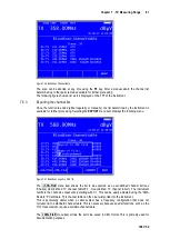
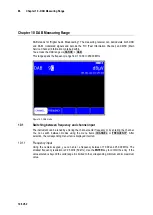
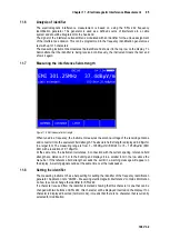
You can enter the desired channel number using the numeric keypad. The channel index (“A”-“F”)
can be entered using keys 1 (for “A”) to 6 (for “F”). Use the
ENTER
key to confirm the entry. Invalid
entries are ignored.
If the measuring receiver is tuned and the menu item
2.FUNCTION
is not inverted, you can set the
previous or next channel using the ← and → keys. In this way, you can key in the channels one by
one.
10.2
Scan
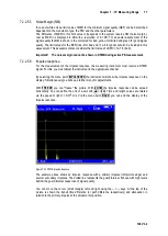
You can use this function to scan the entire range for DAB/DAB+ signals. For this, you must switch
the instrument to channel input mode.
In the DAB operating mode, the arrow keys have a dual function. After entry of a new channel, the
menu item
2.FUNCTION
is inverted.
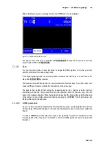
That means that the MPEG decoder can be operated with the arrow keys.
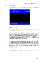
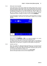
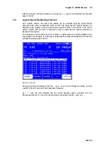
To start the scan, first press the
F5
key in order to activate the first function of the arrow keys.
The scan is then started by first tuning the measuring receiver to a channel at which the scan
should begin. Press the ↑ key to start the scan in the positive direction. Press the ↓ key to do the
same in the negative direction. When the band limit is reached, the scan continues at the other end
of the range. You can end the scan at any time by pressing
ENTER
. “SCAN” is shown on the
display while the scan takes place
10.3
Level measurement
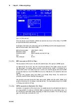
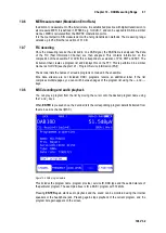
After the measuring receiver is tuned, the automatic attenuation control and level measurement
starts.
The spectra of the signals for DAB have characteristics similar to noise.
The signal energy is spread over the entire channel bandwidth. The measuring receiver uses its
measuring bandwidth to measure the level in the channel center and extrapolates the channel
bandwidth using the bandwidth formula.
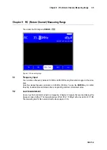
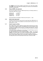
The level measured is indicated on the right side of the display in dBµV with 0.1 dB resolution.
The measuring range extends from 20 to 120 dBµV. The measuring bandwidth is adjusted to the
channel bandwidth of the signal measured. The measurement repetition rate is approx. 3 Hz.
Acoustic level trend
10.3.1
When no line of sight to the measuring instrument exists while lining up an antenna, an acoustic
level trend signal can be switched on. In this case, an acoustic signal is emitted from the speaker.
Its frequency changes in proportion to the measured level. When the level increases, the frequency
goes up and vice versa.
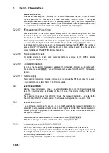
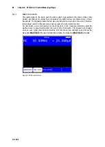
The acoustic signal can be switched on and off via the menu item
ACOU.LEVEL
.
When the acoustic signal is switched on, the menu item is displayed inverted.

