


Chapter 3 - Control and connection elements, pin configurations
21
106 V3.2
3.3
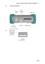
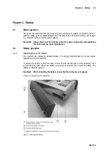
Top section of instrument
Figure 3-3 Top section of instrument
USB-A socket
3.3.1
Pin 1 = V
CC
(+5V)
Pin 2 = Data D -
Pin 3 = Data D +
Pin 4 = GND
Figure 3-4 USB-A socket
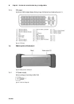
RF Input
75 Ohm
DVI-D
Digital Video
output
USB-A port
Wi-Fi™
Antenna connector
Optical input
CAM/PCMCIA (slot)