54-0215 Rev. C
25
5.2
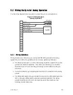
Wiring the Gyro for Analog Operation
Use the wiring diagram below as a guide to connect the gyro to your application.
Figure 10: Wiring Diagram
(Analog Operation)
1
2
3
4
5
6
7
8
9
10
11
12
13
14
15
5 VDC
RETURN
DC SUPPLY
+5 VDC
POWER COMMON
CASE GROUND
RATE - (NEGATIVE)
RATE + (POSITIVE)
CUSTOMER
INTERFACE
GROUND REFERENCE
5.2.1 Wiring Guidelines
Wiring interfaces are critical in a gyro such as the DSP-3000, particularly for analog
signals. Be sure to follow the guidelines below to ensure optimum performance.
•
The chassis ground, pin 3, as well as the housing, should be coupled to the system
ground with minimum impedance. The surface on which the gyro is mounted
should not inject AC noise onto the gyro housing as it will radiate into the gyro
electronics.
•
Current not related to gyro output signal should never be conducted on the analog
ground.
•
The differential output of the gyro should be connected to a differential input of an
ADC or through a differentially configured operational amplifier. The analog
ground should therefore be tied to the signal ground at those interfaces, thus
reducing common mode noise.

