background image

Initial Powering Operations for the Machine Line

KVAL Operation Manual

3-6 

Home the Machine Line


The Machine Line must go through a homing routine before any operations are performed. The 
homing routine sets a zero reference from which each machine measures its movement and cut-
ting process.

If power is lost or any machine is reset, the homing routine must be performed again. Each 
machine has a 

Home

 button on it’s associated 

Main Control Screen

 or the entire machine line can 

be 

Homed

 using the 

Home Machine Line 

button located on the 

Machine Line Screen

.

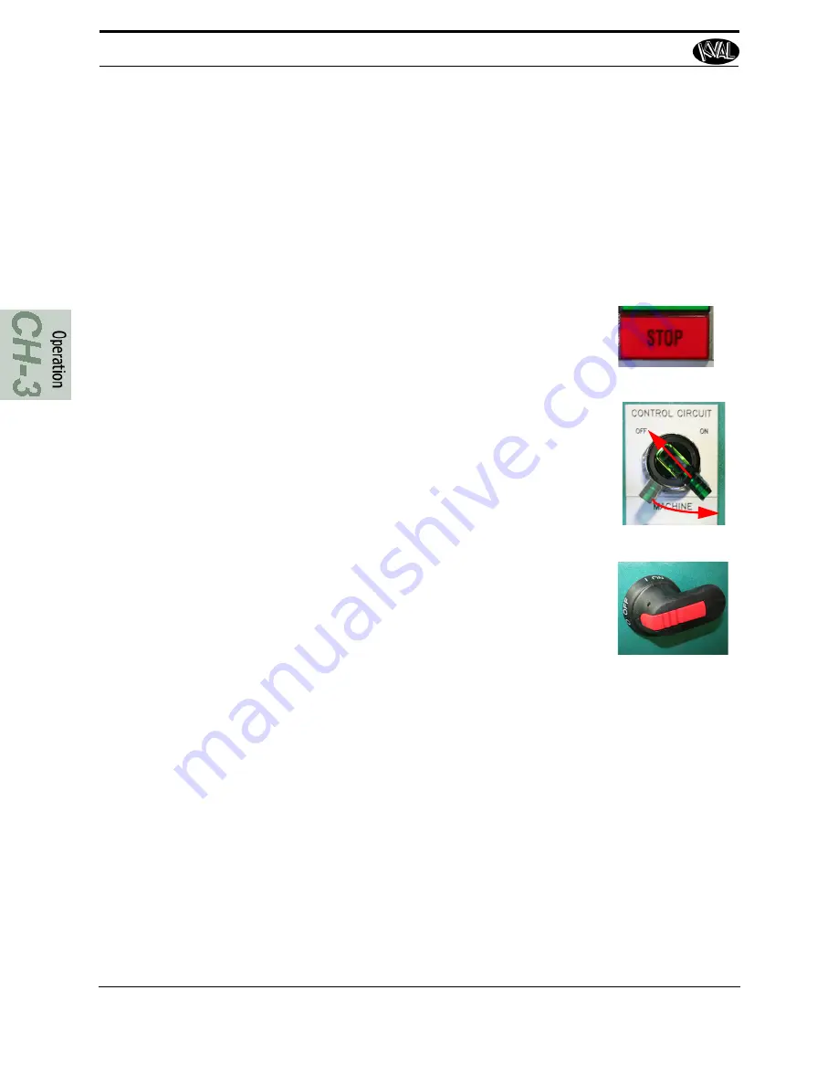
How to Power Down the Machine

1. 

1

2

3

Push the

 Stop

 button for each machine, located on the 

Operator’s Station

2. 

Shut down the operating system, by selecting 

Shutdown


from the Desktop.

Note: 

Make sure Windows is shutdown completely before 

turning off the machine. Hard drive or data may be 
damaged if not turned off in this order.

3. 

Switch the green 

CONTROL CIRCUIT

 switches for each 

machine to the OFF position.

4. 

KVAL also recommends that you turn the disconnect 

switches on the electrical cabinets to OFF; this helps 
reduce possible damage resulting from power surges from 
electrical storms. 

Содержание DL-NCD

Страница 1: ...Innovation Quality Honesty Operation Manual Published October 21 2019 DL NCD Door Lite System Operation Operation Manual ...

Страница 2: ...tered trademark of Microsoft Corporation All other products are trademarks or registered trademarks of their respective holders all rights reserved Reference to these products is not intended to imply affiliation with or sponsorship of Kval Incorporated Contacting KVAL Customer Service For further information about this manual or other Kval Incorpo rated products contact the Customer Support Depar...

Страница 3: ...with our product that is the manual the machinery the software etc What was easy or difficult to use or to learn If you could change something about the design what would it be Please email your comments and suggestions for improve ment to userexperience kvalinc com NOTE This is not a customer support email link For that please refer to the Customer Service contact information above Thank you http...

Страница 4: ...through the KVALCAM Software are also the property of the Licensor and are protected by applicable law 1 Definitions a KVALCAM Software means the KVALCAM computer application installed in the KVAL Machinery and written documentation and materials provided to you as well as any res or updates of such computer application and documentation b Install means storing of the KVALCAM Software in the compu...

Страница 5: ... Tagout Air Supply 1 11 Start Maintenance 1 11 Post Maintenance Steps 1 11 Zero Energy to Start Up 1 12 Getting Help from KVAL 1 14 On Line Help 1 14 Product Return Procedure 1 14 How to Download the Service Application 1 16 Download Application 1 16 Safety Sign Off Sheet 1 19 A Note to the Operator 1 19 Chapter 2 About KvalCAM Summary of the KvalCAM Interface 2 2 Libraries and Machine Line Screen...

Страница 6: ... Edge Hinge Preview 2 23 Appendix About Validation 2 24 About the Validation Screen 2 25 Outline 2 25 About the LiteCutout Feature Detail 2 26 Process 2 26 About the LiteCutout Screen 2 29 About the Work Area Coordinates 2 30 Sample Oval Cut 2 30 Chapter 3 Operation of the Machine Line About the DL NCD 3 2 About the DL NCD Process 3 3 Initial Powering Operations for the Machine Line 3 4 Operator s...

Страница 7: ...out Tool Locations 3 24 About Using Tool Configuration 3 25 Measuring Tool Length 3 25 About Entering Data into the Pop up Menu 3 26 About the Lock Block Tab 3 27 About the Status and Log Screens 3 28 About the Status Screen 3 28 About the Log Screen 3 29 Appendix Description of the Six Light Panel 3 30 Appendix About Backing up the Data 3 31 Chapter 4 Calibration of the Machine Line About Calibra...

Страница 8: ...tep 4 Calibrate the Lock Edge Probe Option 4 14 Lock Edge Probe 4 14 Before Probe Depth Calibration 4 14 Process to Calibrate the Probe Depth 4 15 Step 5 Calibrate Lock Edge Tools Option 4 16 About the Edge Carriage Axis 4 16 Process to Calibrate the Lock Edge Tool 4 16 Step 6 Calibrate the Tool Holder 4 17 About the Manual Tool Change Mode 4 17 4 17 Axis Direction 4 18 About the Step Sequence 4 1...

Страница 9: ...s 5 9 About the Probe Assemblies 5 9 About the Cutter Head with Optional Side Drill Assembly 5 10 About the Tool Holder Rack 5 11 Removing the Tool Holder from the Cutter Head 5 12 Changing a Tool Bit and Using Tool Change Tightening Fixture 5 13 How to Change a Tool Bit 5 14 About Field Safety Scanners 5 16 About the Drop Out Area 5 17 Drop Out Slide Style 5 17 Drop Out Box Style 5 17 About the E...

Страница 10: ...KVAL DL NCD Operation Manual Table of Contents ...

Страница 11: ...ble options page 1 2 Safety First IMPORTANT safety information is described in this section page 1 5 Lockout Tagout Guidelines Procedures describing Lockout Tagout page 1 9 Zero Energy to Start Up Procedure to power up your machine for the first time page 1 12 Getting Help from KVAL This section describes the method to contact the KVAL service center for help The section includes how to get inform...

Страница 12: ... motor for cutting the door is equipped with an automatic tool changer and access to eight 8 additional tool holders placed in a fixture along the fixed side of the machine Programs can call for an automatic tool change to match the spec ified door cutting process RPM adjustment for wood fiberglass or steel doors Individual door light patterns are created at the machine console or remotely using a...

Страница 13: ...alCAM checks the tools and machines available and automatically generates the G Code and optimizes the machining sequence for the entire process Furthermore KvalCAM offers increased supportability and troubleshooting capabilities Newly developed error codes and code definitions quickly identify any problems to the operator or Kval tech For more information regarding the full functionality and bene...

Страница 14: ...es and how to use the interfaces 5 Tour of DL NCD Identification and descriptions of the DL NCD machine assemblies Chapter Title Description 1 Introduction Safety Information 2 System IT Admin istration Descriptions of the PLC system and computer system 3 Maintenance Maintenance steps for the machine line 4 Troubleshooting Troubleshooting tips and theory of operation Safety Sheet Sign Off Sheet At...

Страница 15: ...Labels In addition to the nameplate KVAL machines may have other warning labels or decals that pro vide safety information to operators Safety labels should be clearly visible to the operator and must be replaced if missing damaged or illegible There are three types of warning labels or decals DANGER means if the danger is not avoided it will cause death or serious injury WARNING means if the warn...

Страница 16: ...hine is at zero state Never clean the machine while it is running Never walk away from the machine while it is running When the Machine is ON The compressed air system connected to this machine should have a three way air valve for shut off and pressure relief All cylinders on machine are under high pressure and can be very dangerous when activated Before performing any mainte nance or repairs on ...

Страница 17: ...g any repairs or mainte nance lockout and tagout must be installed at all locations All maintenance and repairs to electrical circuitry should only be per formed by a qualified electrician Still has power in OFF position Electrical Prior to performing any maintenance repairs cleaning or when clearing jammed debris you must disconnect tag out or lock out the electrical and air pressure systems This...

Страница 18: ...his machine is in violation of any health or safety regulation STOP pro duction It is your responsibility to immediately protect your employees against any such hazard Additional detailed safety guidelines are included in the operating instructions of this manual KVAL will be pleased to review with you any questions you may have regarding the safe operation of this machine Follow Your Company s Sa...

Страница 19: ...tag on each disconnect Only each operator may remove their own lock and tag Important When many people are all working on the same machine you will need a multiple lockout device such as the one shown here Follow the P R O P E R lockout rule of thumb P Process shutdown R Recognize energy type electrical pneumatic mechanical etc O OFF Shut off all power sources and isolating devices P Place lock an...

Страница 20: ...ng tension weight shifts etc 2 Inform all affected personnel of the eminent shutdown and the duration of the shutdown 3 Obtain locks keys and tags from your employer s lockout center Lockout Tagout Power 4 Turn off machine See Chapter 2 for power down and power up procedures 5 Turn the disconnect switches on ALL electrical and frequency panels to the OFF position Then push the red tab to pop it ou...

Страница 21: ...or repairs may started Post Maintenance Steps 9 After maintenance is completed the person performing the work must ensure all tools spare parts test equipment etc are completely removed and that all guards and safety devices are installed 10 Before removing the locks and tags the person who attached them shall inspect the equipment to ensure that the machine will not be put in an unsafe condition ...

Страница 22: ... restored Remove Locks Each operator must remove his or her own lock and tag This will ensure that all oper ators are in a safe place when the equipment is started Perform Visual Checks If the equipment is too large to see all around it station personnel around the area and sound the personnel alarm before starting the equipment If your operation is more complex your company s comprehensive safety...

Страница 23: ... to your lock Proper lockout tagout can save lives limbs and money Help make your work environment safe for you and your fellow workers Be sure to follow the P R O P E R lockout tagout procedures and that those around you do also Close the Cage Gate Verify all cage gates are securely closed Ensure all safety protocols are in effect ...

Страница 24: ...ation Plate and record the serial number 3 phase volts electrical print number and air print number Air Driven Machines 2 Contact our customer support team In the U S and Canada call 800 553 5825 or fax 707 762 0485 Outside the U S and Canada call 707 762 7367 or fax 707 762 0485 Email address is service kvalinc com Hours 6 00 AM to 4 00 PM Pacific Standard Time Monday through Thursday 6 30 AM to ...

Страница 25: ...o the following questions What is the extent of the failure reason for return What are the relevant error mes sages or error codes How long did it operate Did any other items fail at the same time What was happening when the unit failed e g installing the unit cycling power starting other equipment etc How was the product configured in detail Which if any cables were modified and how With what equ...

Страница 26: ...At the KVAL website select the Support tab Follow the instruc tions on the Support web page 3 Click the Download button to download the application that allows the KVAL technician to have access to the operator sta tion 4 After the download is com pleted double click the program icon Note Web browsers have different methods of downloading programs Below are samples of i e Explorer and Google web b...

Страница 27: ...ame Field Enter your name The KVAL techni cian will use this field to identify this machine Description Enter machine Serial number and issue Indicator Green indicates there is a good connection to the service center If red there could be an issue with a LAN connection Check the connections in the plant 7 After the KVAL Support App is loaded and completed call the KVAL service center 1 800 553 582...

Страница 28: ...How to Download the Service Application KVAL Operation Manual 1 18 ...

Страница 29: ...my company s safety procedures I have read and understand these guidelines Machine Safety Concerns I have been given a tour of the machine and understand all the safety labels E Stops and the actions to take in case of an emergency I will make sure all guards are in place before operation I will turn off the compressed air before loading hardware staples screws etc I will turn off the electrical p...

Страница 30: ...Safety Sign Off Sheet KVAL Operation Manual 1 20 ...

Страница 31: ...The KvalCAM interface uses tabbed navigation to jump to desired screens Chapter 2 at a Glance Section Name Summary Page A one page description of the KvalCAM inter face page 2 2 About the Libraries Screen Description of Libraries Screen Includes job creation job editing loading templates and verifying job creation page 2 3 About the Machine Line Screen Description of the Machine Line Screen Includ...

Страница 32: ...n to jump to desired screens Libraries and Machine Line Screens Below are screen shots that show the programming and machine line program operations Libraries Includes two tabs the Door Job Library and the Feature Group Library Create edit clone delete and download door jobs and door templates Powerful and flexible database of door cuts See About the Libraries Screen on page 2 3 Machine Line View ...

Страница 33: ...to jump to these screens Distinguish between the Door Job and Features Group Libraries One can describe the Features Group Library as a virtual scratch pad and the Door Job Library as the engine to run the door through the cutting process In the Features Group creation screen door cuts an be created and verified by way of the Job Pre view screen In the Door Job creation screen door cuts can be cre...

Страница 34: ...ab then select Door Job Library or Features Group Library Tab depending on desired action Use the buttons at the bottom of the screen to create clone edit or delete jobs or Feature Groups Lock editing capabilities and refresh tabs are also available Note The Door Job and Features Group Library have the same layout and storage for mat ...

Страница 35: ...plate or use existing to run doors Jumps to the Job Creation Screen The Most Common Path way to start the door Machining Process Clone Button Select a Tem plate or Door Job from the list to copy and rename Delete Button Select a Tem plate or Door Job from the list to Delete Refresh Select to re read the data base Unlock Lock If Door jobs or Features Groups are locked click add password to edit the...

Страница 36: ... at this screen Note Sample of face lock and hinge job creations are located in th appendix of this manual See Appendix Job Preview Examples on page 2 21 Note For a sample of validation errors see Appendix About Validation on page 2 24 To create a new Door Job or Template select the Create button at the bottom of the screen To edit or view a created Door Job or Template select the item from the ta...

Страница 37: ...sed Door Parameters Displays the basic parameters of the door being processed If creating a door enter the parameters Door Hand Select the Hand Ori entation of the Door From the drip down menu select Left Hand Right Hand Left Hand Reversed Right Hand Reversed Door Material Select type of material of the Face Hinge side and Lock side of the door Wood Fiber Glass or Steel Note Changes in the door pa...

Страница 38: ...s can be created in the Features Details Menu Add Child Select to create a new child to a group or child Add from Library Select to add a tem plate from the Library Delete Select to delete a Group or Child Notes Tips Color Coded Indicators next to the Child Features are color coded to reflect the location on the door Hinge Edge Lock Edge Hinge Pivot Face Opposite Hinge Pivot Face Top End Bottom En...

Страница 39: ...6 75 36 0 and 65 25 with a reference from the top of the door Coordinate References Set the reference in relation with the cut The reference option will be dis played in Job Preview T Thick Reference Hinge Pivot Face Key Face Opposite Key Face Opposite Hinge Pivot Face L Length Reference Bottom Top W Width Reference Lock Hinge Defined Properties Create a custom property to be used for the selected...

Страница 40: ...ils the parameters of the hinge cut Predrill locations are also included in the example Feature Name Name of The Fea ture Under the Group Feature Type Select type of cut Circle FaceCircle FaceRectangle Hinge Rectangle TeeShape LiteCutout See About the LiteCutout Feature Detail on page 2 26 Door Side Select Door Side Bottom End Top End Hinge Edge Lock Edge Hinge Jamb Lock Jamb Data Table Parameters...

Страница 41: ...ave all a new Door Job or save Edits to a Job Password Protected Add to Queue and Door Qty The first step of door processing Enter the quantity of doors to be pro cessed in the Door Qty Box then select the Add to Queue button to start the process Save as New Make adjustments to an existing cut pattern and save as another file Export to DXF Select the Export to DXF Button to create a blueprint of t...

Страница 42: ...dix Job Preview Examples on page 2 21 2 D Screen Display Area Door Axis Axis changes per Preview Surface selections Preview Surface Preview Surface Select from drop down list to view Bottom End Top End Hinge Edge Lock Edge Hinge Pivot Face Opposite Pivot Face Grid Lines in Change the size of the grid line Scale Percent Displays the mag nification value of the screen pre view Note May use the mouse...

Страница 43: ...ration Manual 2 13 3 D Screen Select the 3 D Tab to display a three dimensional view of the Door Job Right click the mouse to control the movement of the 3 D display The Preview Surfaces are color coded and listed on the display ...

Страница 44: ...elect the Machine Line Tab on the left side of the screen to jump to this screen This includes Menu Description A Machine Activity For each machine a table shows job name quantity of remaining doors doors being processed and status of the machine B Queued Jobs Shows a list of the upcoming jobs C Line Controls Common operations to control the machine line Machine Line Screen ...

Страница 45: ...ts the machines in the line Status Lists the status of each machine Quantity Lists the quantity of doors at the start of the Door Job Job Lists the name of the Job being processed The Job name reflects the name assigned in the Door Job Library Remaining Lists remaining quantity of doors left in the Door Job Templates Descrip tion of the types of cuts that are being used About the Machine Line Scre...

Страница 46: ...he jobs that are going to be processed Commands Select the Remove Button to clear the Job from the list Creation Time List the time when the job is put in queue Job List the file name of the Job Quantity Lists the quantity of doors at the start of the Door Job Template List the File name of the Template About the Machine Line Screen KVAL Operation Manual 2 16 ...

Страница 47: ...ed ON The door will automat ically feed through each machine Auto Feed OFF The feed status must be set the machine Operator s Screen Clear Queued Jobs Press to clear the entire list of door jobs in the Queued Job table Home the Machine Line Press to Home every machine in the line Reset the Machine Line Press to reset the every machine in the line You Must Home the line after this reset is performe...

Страница 48: ...o send machine data to a text file The file may be sent to Service Support if any issues occur Notes may be added to describe the saved file Note Kval recommends backing up locally or to a isolated server Build Info Select to view upper level notes about the current build Exit Select to close the running KvalCAM program Backup Logs Select to save the to save all data from the machine operation Not...

Страница 49: ... out All Feature Groups have their own L T and W location that is separate from the features contained inside This allows the user to quickly move templates to new locations or to duplicate templates in multiple locations by adding new locations to the group Feature Group Name This field is required when saving a new template Feature Features are created by adding children to a feature group All f...

Страница 50: ...only appears if the expression cannot be interpreted to a real number for valida tion while orange appears if the line cannot perform the cut Validation Report Validation Report identifies particular faults that would cause a feature to fail validation Each feature has its own validation tests and will fail if the tests for a valid feature are not satisfied Clicking on a specific test will pro vid...

Страница 51: ...xample of a door lock preview form the face viewpoint Highlight the item from the Feature Tree The Preview Screen will display the cut from the feature group point of view Note the Axis indicator Length and Width for a quick refer ence Note Errors will be indicated by an orange box around the parameter Note Change views by using the manual view buttons at he bottom of the screen Lock Parameters Lo...

Страница 52: ...ght the item from the Feature Tree The Preview Screen will display the cut from the feature group point of view Note the Axis indicator Length and Width for a quick refer ence Note Errors will be indicated by an orange box around the parameter Note Change views by using the manual view buttons at he bottom of the screen S Lock Parameters and Locations ...

Страница 53: ...light the item from the Feature Tree The Preview Screen will display the cut from the feature group point of view Note the Axis indicator Length and Width for a quick refer ence Note Errors will be indicated by an orange box around the parameter Note Change views by using the manual view buttons at he bottom of the screen Lock Parameters and Locations ...

Страница 54: ... errors in the door job will be highlighted with instructions to fix the error This is a sample of an incorrect depth parameter Validation error is discovered when creat ing a Door Job 1 An Orange Box will highlight the group with an error In this sample the Lock Edge Child has an error 2 To investigate the error select the Vali dation Report button at the bottom of the display 1 2 ...

Страница 55: ...ame ter Shows the hierarchical outline of tested parameters Outline Tile displays the dimensions of the Feature Group Each child node is listed under the selected group In this case there is an error in the Lock Edge routine Either change the depth in the table of the Feature Table or select Commander 3 Tool Con fig Lock Tools and change the depth in the Depth Stop Z Loca tion field to match desir...

Страница 56: ...alCam to be processed Process This procedure details the steps to crate a new LiteCutout Feature For detailed descriptions of the LiteCutout Screen see About the LiteCutout Screen on page 2 29 To add a new LiteCutout 1 If needed add a Feature Group 2 Add a Child to the Feature Tree 3 Select LiteCutout from the Feature Type drop down menu and add a Feature Name add a Feature Name 4 Select the Edit ...

Страница 57: ...e LiteCutout working space is displayed 6 Select the Import DXF Button and select the desired file from your directory If needed manipulate the shape Import DXF file In this example an oval DXF file was imported 7 or add the file into KvalCAM by selecting the OK Button ...

Страница 58: ...About the LiteCutout Feature Detail KVAL Operation Manual 2 28 8 Input WLocation and LLocation to put the cut onto the door 9 If finished with editing the Door Job run the door ...

Страница 59: ... LiteCutout Screen This section describes selections on the LiteCutout Screen About the Work Areas Zoom In and Out with Mouse Move shape vertically and horizontally with Slide Bars Select a vertex point on the cutting path and manipulate the shape Expand or collapse windows ...

Страница 60: ... goes toward the Hinge Edge Y Negative goes toward the Lock Edge X Positive goes toward the Top of the Door X Negative goes toward the Bottom of the Door Sample Oval Cut Vertex Point Points may be added with the Insert Vertex Button in the bottom bar Cutting Path Width varies with the MaxToolDiameter size that is inputed Knockout Point Points may be added with the Insert Knock Out Point button loc...

Страница 61: ... settings of the Work Area Selected Details Displays the details of a selected point on the DXF file The Shape may be manipulated with a mouse or by populating the designated input boxes OK Send to KvalCAM Cancel Stop work and go back to KvalCam Insert Vertex Insert another Vertex point along the cutting path Delete Selected Delete any selected point on the shape About the LiteCutout Feature Detai...

Страница 62: ...About the LiteCutout Feature Detail KVAL Operation Manual 2 32 ...

Страница 63: ...at a Glance Section Name Summary Page A Summary of the entire machine line page 3 2 Initial Power Operations Description of powering up the line from the off state Includes Power down description Six Light Panel and homing the machine line page 3 4 Machine Start Summary A quick summary of running a door through the machine page 3 8 About Machine Process Describes the process of the machine page 3 ...

Страница 64: ...n Manual 3 2 About the DL NCD The DL NCD is a computer controlled machine designed to precisely machine the face of a door for Door Light patterns and lock patterns Below is a typical location of the DL NCD in a Door Processing Line ...

Страница 65: ...ed and the machining process is started The quantity of doors the type of machin ing is determined by user interface 4 Door is fed to next machine for further processing 2 The door is positioned against the stop clamp the door and is automatically adjusted to the doors width Actions Pull Auto feed door in from the previousmachine Roll the door into the machine Actions Door Stops Position Door Clam...

Страница 66: ...tions of door machining Manually control the door path and process through the line Machine diag nostics are included as well as internet sup port and connectivity for remote support via our Service Support Touch Screen Interface Main Control of Entire Machine Line Download G code and Templates to set the specifications of door machining Manually control the door path and process through the line ...

Страница 67: ...p has been activated 3 Make sure the electrical disconnect each electrical cabinet is turned to the ON position 4 Switch the green CONTROL CIRCUIT switches to the ON positions They should light up 5 Push the green START MACHINE buttons to boot up the machines Note Boot up may take 2 to 3 minutes 6 All lights on the status light panels on the electrical box should be illuminated See Appendix Descri...

Страница 68: ...ne can be Homed using the Home Machine Line button located on the Machine Line Screen How to Power Down the Machine 1 1 2 3 Push the Stop button for each machine located on the Operator s Station 2 Shut down the operating system by selecting Shutdown from the Desktop Note Make sure Windows is shutdown completely before turning off the machine Hard drive or data may be damaged if not turned off in ...

Страница 69: ...tion Screen will remain on To Resume Normal Operation after an E Stop If an E Stop is activated use the following procedure to recover after the cause of the emergency stop is resolved 1 De activate the E Stop switch by pulling it out 2 Push the START MACHINE button on the operator s station 3 Home the Machine Other Safety Controls Other safety controls can include Gate Latches Sensors are located...

Страница 70: ...ctrical Panel 3 After the computer is completed booting up the KvalCAM User Interface will start automatically Note If starting at the Windows Screen select the KvalCAM icon on the screen Select the Home Machine Line Button Every machine in the line will Home On comple tion each machine status will display Idle in the Machine Feedback Status box After the door has completed the Home sequence Selec...

Страница 71: ...d Stop button located on the Operators Station 2 Shut down the operating system by selecting Shutdown from the Desktop 3 After computer has fully shutdown turn off the Green Control Transformer lever on the Operators Station 4 Turn OFF the Red Power lever the Electrical Panels Machine Line Start Summary KVAL Operation Manual 3 9 ...

Страница 72: ...hines is displayed The machines are constantly polled feeding back their state of operation This feedback is a great tool to instantly view the status of each machine This information can be used to trouble shoot any issues that may occur When activated the tab will highlight Note At the top of the screen the revision of software is dis played ...

Страница 73: ...trol See See About the DL NCD Manual Servo Control Screen on page 3 16 Tool Usage Table to show the tool usage See See About Tool Usage on page 3 20 Tool Config Fine tune the tools parameters for an accurate cut See page 3 22 Calibration Description and instructions to fine tune the servo drives See Chapter 4 Tool Path Preview Investigate the path the tool follows during the cutting pro cess See A...

Страница 74: ...the home sequence on the machine which scans to find a physical reference point on the frame When this point is found the position is stored and then used to calculate the location of all moves during the machine process The home sequence must be performed every time the machine is powered up or reset Reset Machine If a fault occurs that cannot be cleared press the Reset Machine button This button...

Страница 75: ... mode the machine is in normal oper ation Park Current Tool Press to move the tool being used in the cutting process to the tool holder Abort Job Select to stop abort the process of the door that is currently running Current Servo Position Displays the servo position of the cutting head X Y and Z and the width Routine Speed Adjust the speed of the cut Press buttons to use the graduated speeds or s...

Страница 76: ... feed with out machining the door Manual Feed Control Reverse Press and hold the Reverse button to feed back door to the in feed of the machine To stop the feed release the button Forward Press and hold the Forward button to move the door feed to the out feed of the machine To stop the feed release the button Feed Fast Slow Press to toggle between slow or fast speed Width Adjust Move Open Press an...

Страница 77: ... Probe Select to enable or disable the Lock Edge Probe Probe locations on the machine Note Probe locations on this machine can be found in Chapter 5 of this manual Note When the Length and Lock Edge Probes are disabled door length and lock specifications are derived from the Door Job About the Main Control Screen KVAL Operation Manual 3 15 ...

Страница 78: ...KVAL Operation Manual 3 16 About the DL NCD Manual Servo Control Screen Select the Manual Control Tab At this screen control the servos manually and run a process to fine tune the tool pickup routine FIGURE 3 2 Manual Control Screen for the DL NCD ...

Страница 79: ...e the car riage forward Release the button to stop the carriage The carriage will also stop if the positive travel limit eye is activated Speed Press to change speed of operation 100 percent is the maximum speed of the level selected from the main screen by way of the Cut Routine Speed buttons The Forward Z axis plunges into the door The Reverse Z retracts from the door X Forward X Reverse Y Forwa...

Страница 80: ...e In normal production the Step Mode can be ON or OFF No interference with production will occur About the DL NCD Manual Servo Control Screen KVAL Operation Manual 3 18 Process Note If calibrating calibrating one tool will calibrate all tools For calibration infor mation see Step 6 Calibrate the Tool Holder on page 4 17 This should be a two person operation with one at the Operator Station and one...

Страница 81: ...About the Main Control Section Edge Servo Control Adjust the speed of the Edge Cutter in the Y axis vertical About the DL NCD Manual Servo Control Screen KVAL Operation Manual 3 19 ...

Страница 82: ... table select the desired column title Name This is the name assigned to the tool at the Tool Configuration Screen Tool Type This is the type of tool assigned in the Tool Configuration Screen Start Date This is the date the tool was changed This is set by the Clear Button Usage The amount of hours that the tool has been used The counter starts after the Clear But ton has been selected for that too...

Страница 83: ...machine can be viewed This sequence can be essential if troubleshooting calibrating or checking the wear of a tool Dis crepancies can be viewed before cutting into a door saving product and time The figure below displays a sample of a good Deep Mortise Cut 1 Select a G Code routine form the drop down menu 2 Select the Render Button 3 View the path of the tool on the screen Step 1 Step 2 Step 3 Cir...

Страница 84: ...is manual see page 3 24 General Operating Controls The Tool Config Screen contains a sample of the following List of the available tools Pop up menus to enter information about each tool Specifications The ability to adjust the method of chisel operation during machining The ability to enable or disable specific tool slots The ability to name the tools to familiar names The ability to lock and unl...

Страница 85: ... Click OK 3 Ready to Enter Data About the Tool Pop up Screens Each tool slot has versatility to choose between entering router or chisel information Click the Enable Check Box to clear the box and disable the tool Below are samples of the pop up windows available Sample Drill Configuration Pop Ups Drill Pop up Sample Drill Pop up Disabled Sample Sample Router Configuration Pop Ups Router Pop up Sa...

Страница 86: ... Tabs KVAL Operation Manual 3 24 About Tool Locations Tool locations are identified by slots See the figures below for the locations and identifications Note Below are factory suggested locations Identification of Slots can be altered through this menu Face Tools Lock Tool ...

Страница 87: ...ength 1 Measure the parameters listed below Total Tool Length The distance from the collet face to the tool s tip Tool Cutting Length The distance from start of the cutting area to the tip of the bit Tool Point Length From the point where the point starts to the end of the bit 2 Update the data in the Tool Config Group Important The accuracy of the data Tool Config is important Any errors could da...

Страница 88: ...ing Data into the Pop up Menu Insert specifications of the tools being used to make the cuts Ability to name the tools to user defined descriptions Customize the tools to reflect the actual tool parameters making the most accurate cuts Ability to define cut operation ...

Страница 89: ...age The cutter head will slow down to this percent age when is reaches the lock block location 3 Enter location of the lock block a Wood FG Speed Percent Modifies the feed rate to cut wood or fiberglass skin doors b Steel Speed Percent Modifies the feed rate to cut steel skin doors c Bottom of Door to Block The location of the block with the bottom of the door as a reference d Extent Along Length ...

Страница 90: ...e machine can be viewed The feedback includes times dates and machine status Status includes a True flag if the assembly is in operation or a False flag if not in operation Also status can include data and motor states idle operation The data can be filtered to observe certain aspects of the operation of the machine This tool is great for troubleshooting to locate faulty assemblies Filter Data Sta...

Страница 91: ...achine sections or functions The top line will have the most cur rent routine that is running The codes are color coded Red Error Green Report is a non issue Yellow Warning If the machine issue can not be resolved call KVAL Inc 1 800 553 5825 Have any error code that is displayed ready to give the KVAL representative This will aid in troubleshooting and shorten down time FIGURE 3 6 Log Screen ...

Страница 92: ...secondary side of trans former 2 Overload Relay Checks the Overload Relay in the E Box In some cases this circuit is jumped In these cases it should always light when the Control Power turns on 3 E Stop All gates are closed and the E stops are not activated when this light is on 4 Stop This light will be on if Machine Stop button is deactivated 5 Start This light will be on once the Machine Start ...

Страница 93: ...ta from the machine operation Notes can be added to describe the saved file Backup and Export Click to send machine data to a text file The file may be sent to Service Support if any issues occur Notes may be added to describe the saved file Note Kval recommends backing up locally and to a isolated server Build Info Click to view upper level notes about the cur rent build Release Notes Click to op...

Страница 94: ...Appendix About Backing up the Data KVAL Operation Manual 3 32 ...

Страница 95: ...ection Name Summary Page Descriptions of the Calibration Menus Tips to look for before calibrating page 4 2 Descriptions of the Calibration Tabs page 4 3 Descriptions of how to use the calibration screens page 4 6 Descriptions of the calibration available page 4 8 About Calibration About the Calibration Tabs How to Enter Calibration Data About the Calibration Screen ...

Страница 96: ...ibration Reference Cut This chapter describes the Calibration Menus In the Calibration Menus offsets are entered to calibrate assemblies in the machine See About the Calibration Tabs on page 4 3 Before you Calibrate Before you start calibration check for the following common issues 1 Is the loaded setup correct for the current cut 2 Check tools for wear 3 Is the correct Calibration loaded 4 Are th...

Страница 97: ... Log Screens for error reporting Finding errors from these screens will help localize problem areas Note If the machine issues can not be resolved call KVAL Inc 1 800 553 5825 Have any error code that is displayed ready to give the KVAL representative This will aid in troubleshooting and shorten down time Access to the Calibration Adjustments Buttons to unlock access to calibration save a calibrat...

Страница 98: ...ation Option Access to the calibration is password protected Optional 1 Select the Unlock button 2 At the Password pop up enter the password and select OK to continue 3 The calibration message will change from a red Calibration is Locked to a green Calibration is Unlocked ...

Страница 99: ... cut second finger and thumb at right angle to each other The first finger represents the positive direction of the Z Axis the thumb represents the positive direc tion of the Y Axis then second finger represents the positive the direction of the X Axis Door Edge Axis Directions Option Stand at the Lock Side of Door point at the edge of the door with the left hand rule to determine axis direction X...

Страница 100: ... of the Base and the Offset Combine Merges the offset number to the base Base Is the result of the Combine selec tion The merge of the Offset and the Base Offset Enter the desired offset to bring into calibration Save Button Select to store the calibration Below are general instructions to perform a calibration 1 Check for deviations between the expected machining and the actual machining Determin...

Страница 101: ... a Restore Point 1 Select the Restore Points button 2 Select the Save Current button from the pop up window save current calibration 3 Name and enter to save To Load or Delete a Restore Point 1 Select the restore point from the menu 2 Select the Load button to use the calibration Select the Load button to load 3 Select the Delete button to delete the point ...

Страница 102: ...Carriage Axes Adjust the location of the 3 axes X Y and Z of the Face Carriage Head Edge Carriage Axes Option Adjust the location of the 3 axes X Y and Z of the Edge Carriage Head Tool Holder Adjust the position and approach of the Carriage Head at the Tool Holder Rack Axes X Y and Z Face Tools Adjust the diameter of each Face tool Lock Edge Tool Option Adjust the Diameter and Axes X Y and Z of th...

Страница 103: ...alibration enter offsets in the Length Probe Calibration Box and the Width Adjust Cali bration Box A known good door is send through the machine multiple times Length Adjust Width Adjust Process to Calibrate the Length and Width 1 Measure a known good door These measurements are used to compare feed back at the Log Screen a The door should be true and be considered a calibration reference b Door s...

Страница 104: ...ast 3 times Each time capturing the measurements from the Log Viewer 9 Reverse the door and re feed it at least 3 times Each time capturing the measure ments from the Log Viewer 10 To get the average add up all data collected from the Log Viewer and divide by the number of times the door was fed in 11 Compare the actual measured data with the calculated data 12 If the width measurement feedback is...

Страница 105: ...he door Measure the parameters of the square Process to Calibrate the Face Tools 1 Before calibrating the tools update the Tool Configuration of the tool being calibrated See About Using Tool Configuration on page 3 25 2 Create a FaceRectangle Door Job of your choice 3 Add Door Job to the Queue 4 Once the cut has been made check the parameter length and width of the cut 5 Increase or decrease the ...

Страница 106: ...menu Before Calibration Note It is recommended to verify the Tool Config settings before calibrating the plunge cut Z Axis This is a global calibration Therefore by calibrating other tools may be out of calibration For directions on how to use the configuration menus see About Using Tool Configuration on page 3 25 Face Carriage Axes Calibrations Using the left hand rule verify the the X Y and Z ax...

Страница 107: ...achined check location of the cut If the cut is not in the specifica tions find which needs to be calibrated 4 Perform the Left Hand Rule at the lock side of the door to determine axis direction See illustration below If the location is out of specification in the length of the door the X Axis needs to be adjusted If the location is out of specification in the width of the door the Y Axis needs to...

Страница 108: ... about entering calibration data see How to Enter Calibration Data on page 4 6 Lock Edge Probe At the Calibration Screen select Door Stops and Probes to display the calibration menu Before Probe Depth Calibration Before calibrating the Lock Probe depth Z Axis verify the X Axis and Y Axis This is a visual test Run a Door Job Check the Depth Probe Pad position as it touches the door edge Pad on prob...

Страница 109: ...Step 1 Calibrate the Length and Width on page 4 9 Note The depth position of the probe will influence the depth of the cut for edge tools 1 Create a Door Job with edge work 2 Add the door to the Queue 3 Feed the door into the machine 4 Select the Log Tab and check the latest Edge Probe feedback located under the Mes sages Column 5 If a positive value is displayed enter a positive offset to zero th...

Страница 110: ...e 2 Add Door Job to the Queue 3 Once the cut is machined measure the length width and depth positions of the cut If the cut is not in the specification determine which axes need to be calibrated 4 Perform the Left Hand Rule pointed at the cut lock to determine axis direction See illustration below If the length position of the lock cut is out of specification the X Axis needs to be adjusted If the...

Страница 111: ...s located under the Maintenance Tab Check location of the Cutter Head Tool Holder against the Tool Holder Rack then enter offsets into the X Axis Y Axis and Z Axis cali bration boxes to align to the Tool Holder About the Manual Tool Change Mode This calibration is best used with the Manual Tool Change Mode When activated the Cutter Head can be moved in repeatable steps toward away up and down with...

Страница 112: ...Negative Y Positive 2 5 inches FIGURE 4 8 Axis Direction About the Step Sequence The step sequence will follow different paths depending if the tool is loaded in the Cutter Head or not loaded If a tool is loaded into the Cutter Head the tool must be manually deposited to the Tool Holder Rack to begin the calibration process Process to Calibrate the Tool Holder This should be a two person operation...

Страница 113: ...s directly over the tool ver ify alignment of the Tool Holder to Tool Enter any offsets if needed see Figure 4 8 above for axis direction 6 When directed by the status message verify the distance from the lip of the Tool Holder to the ledge of the Tool 7 At completion verify that the tool is picked up from the Tool Rack and locked into the Tool Holder and the tool is placed and released into the T...

Страница 114: ...tion of the knockout strike For instructions about entering calibration data see How to Enter Calibration Data on page 4 6 Process to Calibrate the Slug Knockout 1 Create a Door Job of a a FaceRectangle of 5 0 by 5 0 1 Add Door Job to the Queue 2 After the cut has been completed verify the knockout plunge hits at the center of the cut 3 Adjust the X Axis and Y Axis offsets until plunge is centered...

Страница 115: ...out entering calibration data see How to Enter Calibration Data on page 4 6 U l Off t Process to Calibrate the Clamp Assembly 1 Enter the desired width of the fence in unclamping mode 2 Slide door into the machine and firmly press it against the fixed fence 3 There should be about 1 4 of a gap from the movable fence and the door edge 4 Repeat until condition has been met ...

Страница 116: ...Calibrate the Door Stop KVAL Operation Manual 4 22 Step 9 Calibrate the Door Stop About the Stop 1 Calibration Do not adjust the Stop 1 calibration The calibration is to be used by trained Service Technicians ...

Страница 117: ...llustration below identifies the servomotor locations on the machine Each servomotor corre sponds to the calibration adjustments in this chapter Width Servo Motor Connected to Speed Reducer Z Axis Servo Motor Main Cutter X Axis Servo Motor 1 of 2 Y Axis Servo Motor Y Axis Servo Motor Lock Edge Prep X Axis Servo Motor 2 of 2 ...

Страница 118: ...Appendix Servo Motor Drive Assembly Locations KVAL Operation Manual 4 24 ...

Страница 119: ...scription of the Operator s Station controls page 5 3 Around the Machine A tour of the Machine assemblies page 5 5 About the Probes A description of the encoder driven probes on the machine page 5 9 About the Cutter Head Description of the Cutter Head assembly page 5 10 About the Tool Holder Rack Description of the Tool Holder Rack Including steps to change a tool page 5 11 About the Drop Out Area...

Страница 120: ...machine Drop Out Area Slide to Collect Cutouts Movable Fence Air Supply Sensors Located Throughout Machine Stationary Fence Electrical Panel 2 Electrical Panel 1 Tool Holder Rack Cutter Head Operator s Station Option R Reverse Feed Door can feed in at either end of machine Door Stop Length Probe Side Drill Opt Width Probe Side B Side A FIGURE 5 1 Top View of the DL NCD ...

Страница 121: ...tor station with interfaces for an ON 3 Feeder Touch Screen Interface KvalCam interface Main Control Panel Power Up and Power Down machines Start and stop the door pro cess pause doors in the Feeder and Stacker Emergency Stop See Initial Powering Operations for the Machine Line on page 3 4 Keyboard Enter data and interact with Touch Screen Control Circuit Turns on the circuit to give the machine p...

Страница 122: ... and Side B Some machines may have reverse feed This allows inputting the door from either side Check your machine for which options is included Reverse Feed Normal Feed Infeed Outfeed Infeed Outfeed Outfeed Infeed Side B Side A FIGURE 5 3 About Side A and Side B ...

Страница 123: ...ir Nozzles The automatic blow off consists of a bank of high pressure air nozzles to clean dust and debris as the door feeds in or out of the DL NCD Note To manually turn off the air use the slide value located on the side of the machine FIGURE 5 5 Air Nozzles for Blow Off of Debris Light Color State Description Blue Solid Door in machine with no work loaded Feed thru Green Solid Machine is busy G...

Страница 124: ...wo classifications of sensors on the DL NCD Photo Electronic and Inductive Proximity Sensor Photo Eye Detector Emitter and Receiver in one package Proximity Detector Senses metallic objects Proximity Sensors Used on Cylinders FIGURE 5 6 Examples of Sensor Tool Select Senors Probe Return Sensor Door In Sensor OutFeed Sensor Door Width Sensor Door InFeed Sensor Probe Crash Sensor Mid Machine Sensor ...

Страница 125: ...The I designators are inputs and the Q designators are outputs Figures 5 3 and 5 4 show the X Y and Z Axis homing sen sors Z Limit Neg Z Home Z In Tool Changer Z Limit Pos Dust Hood Up Motor Release Tool FIGURE 6 Z Axis Sensors Y Limit Pos Y Limit Neg Y Limit Home X Limit Pos X Limit Neg I 2002 X Home FIGURE 7 X and Y Axis Homing Sensors ...

Страница 126: ...top System The door stops are controlled by an air cylinder The stop will pop up when activated A door pusher on the out feed end of the machine pushes the door up against the stop The width adjust clamps the door tight Door Stop Cylinder FIGURE 5 1 Stop Assembly ...

Страница 127: ...ion This refer ence is used as a comparative point resulting in a highly accurate measurement The encoder assembly is identified as a probe Important If calibrating calibrate the probes first See Chapter 3 in this manual Typical Encoder About the Probe Assemblies The probe assemblies use encoders to get accurate measurements of the door The measurement results are fed back to the KvalCAM software ...

Страница 128: ...ghts in doors made of fiberglass steel or wood A cylinder attached to a metal block knocks out cut portions of the door to the drop out area The Cutter Head movements and cutting routines are driven by template software manual input and the PLC The Cutter Head Motor The motor is automatically driven to the Tool Holder Rack to retrieve the Tool Holder Tool Holder Location Knock Out Assembly Side Dr...

Страница 129: ...er positions are empty This is only done if a scan has not been done since the access gate was last opened 3 The machine moves first to the empty location where the current tool is to be returned to and returns the tool After the current tool is returned the head moves to the location of the next tool to be used and picks it up 4 When the tool change is complete the DL NCD head moves to the cut st...

Страница 130: ...1 Turn off power and follow lockout and tagout proce dures See Lockout Tagout Guidelines on page 1 8 2 Grasp the Tool Holder firmly by the Collet Nut 3 While still gasping the Tool Holder find the Tool Release Button pull until it clicks ON Leave the button in the On position for now 4 Slide the Tool Holder down and away from the motor Set the old tool aside 5 Using one hand insert the new Tool Ho...

Страница 131: ...hange Tightening Fix ture and enter data into the Tool Setup Group Note The HSD Motors use two types of Tool Holders HSK and V Flange Both types are described here Verify which type your machine uses Collet Collet Nut Bit Assembled Tool Holder V Flange Spindle HSK Tool Holder Option V Flange Spindle Tool Holder Option Collet Collet Nut HSK Flange Spindle FIGURE 5 2 Exploded and Assembled Views of ...

Страница 132: ...nap into place automatically when aligned correctly FIGURE 5 3 Using Tool Change Fixture 2 Use the collet wrench to loosen the collet nut freeing the bit 3 Remove the old bit clean the collet with compressed air Note Never use a torque wrench to loosen hardware It could damage the wrench 4 Check collet for bluing or damage Note Bluing is a condition that occurs when the collet is overheated The ov...

Страница 133: ...ameters listed below Total Tool Length The distance from the collet face to the tool s tip of the pit Tool Cutting Length The distance from start of the cutting area to the tip of the bit Tool Point Length From the point where the point starts to the end of the bit 8 Update the data in the Tool Config Group if needed Important The accuracy of the data Tool Config Group is important Any errors coul...

Страница 134: ...en the scanner will stop the machine As soon as an person or thing enters the protec tive field the safety laser scanner signals the machine to stop To recover if the field is broken 1 Push the Start Machine button on the operator s station 2 Home the Machine 3 Restart process A Generalized sample of the laser safety Coverage Laser Warnings On some machines laser indicators are used to set boundar...

Страница 135: ...eject out and could cause body inju ries if operator is not paying attention Drop Out Slide Style Drop Out Slide The debris from the cutting process drops below to a roller assembly to collect the rem nants slugs in a common area FIGURE 5 4 Drop Out Rollers Drop Out Box Style Drop Out Box The debris from the cutting process drops below to a crate When crate is full open the gate and pull it out an...

Страница 136: ...al components Refer the machine s elec trical prints for in depth information The Main Electrical Panel Supplies voltages to the machine Contains the PLC Programmable Logic Controller Contains servo drives to interact with the servo motors The High Frequency Panel Supplies voltages to the machine Contains the PLC interface VFDs Variable Frequency Drives to interact with the cutter motor and the fe...

Страница 137: ...4 VDC and 110 VAC Terminals Relays VFDs Fixed Feed Move Feed Cutter High Voltage Input Fuses DL NCD High Freq Panel Fan Power Outlet About the Electrical Panels KVAL Operation Manual 5 19 FIGURE 5 7 High Frequency ...

Страница 138: ...r exam ple door sensors width adjusts and tool interfaces PLC Interface Top Ethernet cable is from PLC Bottom Ethernet goes to Cutter Node Inputs and Outputs FIGURE 5 8 Frame Node About the Cutter Node The Cutter Node is connected to the PLC by way of the Frame Node and is located on the cutter head s fixed side of the machine This node interfaces with inputs and outputs of the cutter head to the ...

Страница 139: ...About the Electrical Panels KVAL Operation Manual 5 21 I ...

Страница 140: ...etting help 1 14 L location of Door Length Feeler 5 9 lockout and tagout Guidelines 1 12 lockout procedure 1 10 log screen description 3 29 M main electrical panel description 5 18 manual operation interface 3 21 menu map 2 2 O operator s tour top view 3 2 overload relay light description 3 30 P power lock out procedure 1 10 powering up and down machine 3 5 product return procedure 1 14 R remote o...

Страница 141: ...Index 1 2 Kval DL NCD power up 3 5 Start Sequence 3 12 stop light description 3 30 T tagout procedure 1 10 Z zero energy start up clean up 1 12 inspect 1 12 ...

Страница 142: ......

Страница 143: ......

Страница 144: ...partment Kval Incorporated 825 Petaluma Boulevard South Petaluma CA 94952 Contacting KVAL Phone and Fax In the U S and Canada call 800 553 5825 or fax 707 762 0485 Outside the U S and Canada call 707 762 7367 or fax 707 762 0485 Email service kvalinc com http www kvalinc com ...

Отзывы: