6 | Function description
Editing the soldering profile in the [Profile management] tab and changing it permanently
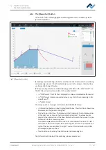
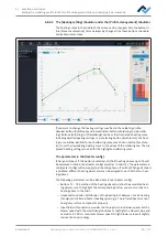
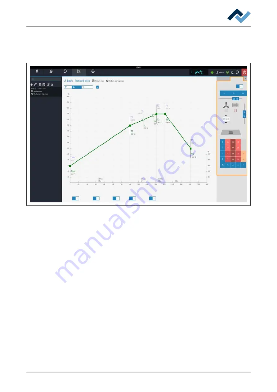
6.8.3.2 The [Heating setting] tabulator under the [Profile management] tabulator
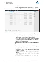
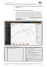
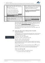
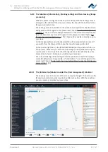
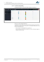
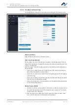
The heating curves in the middle of the screen can be changed. Also the buttons in
line [Process automation] (6) can always be changed. Use these buttons to enable
or disable process steps.
Combined
Rework
Archive
User administration
Profile management
Administration
S T A R T /
R E F E R E N C E
Desoldering
Change all zones
Search
Heater config
Information
Top
Placement
Inspection
Soldering
Inspection
Soldering
Desoldering
Synchronize
Process automation
Bottom
Time
If you want to change the heating settings specified in the soldering profile,
deselect button [Combined] and instead select buttons [Soldering] or [Desolder-
ing]. Buttons [Soldering] or [Desoldering] can have their respective heating curve
including detailed heating settings or, by selecting button [Synchronize], the heat-
ing curve will be identical for both soldering processes. Click on button [Synchron-
ize] to set the desoldering heating curve to the values of the soldering one. The dis-
played heating settings are valid for the highlighted soldering curve.
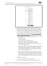
The parameters in tab [Heater config]
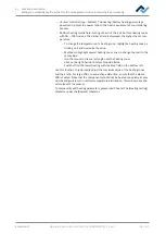
[Change all zones]: if this button is selected, all [Tinit] heating phases up to T4 will
be displayed in blue in tab [Heater config] as well as in chart (4). The parameters in
tab [Heater config] will now apply to all heating phases. If button [Change all zones]
is disabled, different heating parameters can be assigned to each of the four heat-
ing phases.
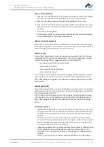
The following parameters can be edited here in tab [Heater config]:
– Buttons T1 – T4: Selection of the heating phase to define the associated heat-
ing parameters. To highlight the corresponding button, you can also click on a
heating phase in the chart.
– Horizontal controller: Distribution of top heating in % between hot air heating
(fan sign) and infrared heater (heating spiral sign). The infrared heater cannot
heat glossy surface components properly.
– Input field with round arrow under the fan logo: Hot-air blower speed. Set the
blower speed with the small triangle buttons or highlight the blower value and
overwrite it. 100 % = maximum blower speed. A high blower value will slightly
reduce the hot-air energy.
Ersa GmbH
Operating instructions HR 550 XL EN 3BA00247-01 | Rev. 1
88 / 157
Содержание HR 550 XL
Страница 2: ......
Страница 6: ......
Страница 22: ...2 Technical data PC system requirements Ersa GmbH Operating instructions HR 550 XL EN 3BA00247 01 Rev 1 22 157...
Страница 153: ...9 Spare and wear parts Spare parts Ersa GmbH Operating instructions HR 550 XL EN 3BA00247 01 Rev 1 153 157...
Страница 156: ...10 Annex EC Declaration of Conformity Ersa GmbH Operating instructions HR 550 XL EN 3BA00247 01 Rev 1 156 157...
Страница 157: ......

