7 | Tutorial – Soldering or desoldering a component
Task 6 “Inspection”
7.12 Task 6 “Inspection”
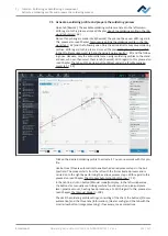
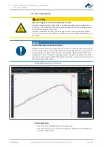
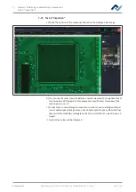
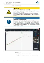
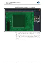
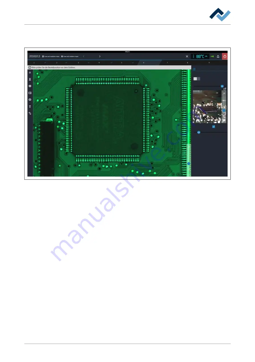
a) Check the position of the component based on the displayed live image.
Alignment
Desoldering
Alignment
Release
Inspection
Provide
Inspection
Soldering
Complete
Parameters
Green light intensity
Brighter
Automatic brightness
Split optics
Next
Back
Darker
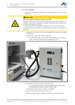
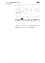
b) You can use the lever to switch between normal view and the telephoto lens of
the Vision box. With regard to this, please also read Chapter Overview of the
machine parts, no. 11.
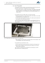
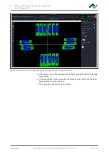
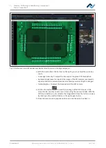
c) For example, in case of large components, in order to see an enlarged compar-
ison of widely spaced image areas, click on button [Split optics]. Now click four
times with the small blue rectangle on the four points that you want to see en-
larged.
ð
A split screen view will be displayed.
Ersa GmbH
Operating instructions HR 550 XL EN 3BA00247-01 | Rev. 1
135 / 157
Содержание HR 550 XL
Страница 2: ......
Страница 6: ......
Страница 22: ...2 Technical data PC system requirements Ersa GmbH Operating instructions HR 550 XL EN 3BA00247 01 Rev 1 22 157...
Страница 153: ...9 Spare and wear parts Spare parts Ersa GmbH Operating instructions HR 550 XL EN 3BA00247 01 Rev 1 153 157...
Страница 156: ...10 Annex EC Declaration of Conformity Ersa GmbH Operating instructions HR 550 XL EN 3BA00247 01 Rev 1 156 157...
Страница 157: ......

