6 | Function description
The chart in the [Profile management] tabulator
6.9 The chart in the [Profile management] tabulator
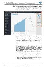
Under tab [Profile settings], chart (4) with the heating curves will be displayed in
the middle of the screen and, below, the button row for the [Process automation ]
(6). The heating curves can be changed here.
Rework
Archive
User administration
Profile management
Administration
Manual mode
Start
Desoldering
Name
Placement
Profile settings
Search
Heater config
Information
Board
Component
Control sensor
Adaptor (head)
Dip mode
Placement mode
Drop height
TC1
Distance 50 mm
No automation
Placement
Nozzle
Heating head position
Placement
Inspection
Soldering
Inspection
Soldering
Desoldering
Synchronize
Process automation
Combined
Component tray
Pickup mode
Time
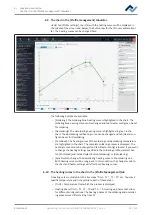
The following buttons are available:
– [Soldering]: The soldering blue heating curve is highlighted in the chart. The
soldering blue heating curve can be changed and tab [Heater config] can be set
for soldering
– [Desoldering]: The desoldering heating curve is highlighted in green in the
chart. The desoldering red heating curve can be changed and tab [Heater con-
figcan be set for desoldering.
– [Combined]: The heating curves of the soldering and desoldering temperature
are highlighted in the chart. The complete soldering process is displayed. The
heating curves cannot be changed and tab [Heater config] is locked. If you want
to change the heating settings specified in the soldering profile, deselect but-
ton [Combined] and instead select button [Soldering] or [Desoldering].
– [Synchronize]: changes the desoldering heating curve to the soldering one.
Both heating curves will be congruent. In this condition, the changes made to
the chart and heater settings will affect both heating curves.
6.10 The heating curves in the chart in the [Profile Management] tab
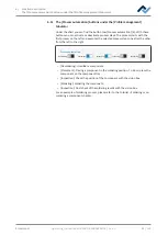
A heating curve is divided into the five steps “Tinit – T1“, „T1 – T2“ etc. You may a
specific temperature and time profile to each of these steps.
– [Tinit] = Temperature from which the process is displayed.
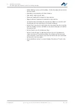
– Heating phase [Tinit] – T1, T1 – T2 and T2 – T3: Heating-up phases that allow
for different configurations. The heating phases of the soldering and unsolder-
ing process may differ starting from T2 .
Ersa GmbH
Operating_instructions HR 500 DE 3BA00246-01 | Rev. 1
82 / 124
Содержание HR 500
Страница 2: ......
Страница 6: ......
Страница 20: ...2 Technical data PC system requirements Ersa GmbH Operating_instructions HR 500 DE 3BA00246 01 Rev 1 20 124 ...


