7 | Tutorial – Soldering or unsoldering a component
Work step 3 “Position” and clean the desoldering point
7.9 Work step 3 “Position” and clean the desoldering point
The desoldered component is positioned on the component tray.
If you want to solder a new component at the desoldering point, you should re-
move any residual solder from the desoldering point:
CAUTION
Risk of burning due to heated machine parts and PCB!
All heated machine parts as well as the surrounding housing parts and product sup-
port frame, the circuit board and the components become hot even during warm-up
to the process temperature [Tinit]!
Parts are particularly hot during the soldering process! After the soldering process,
wait until the device and the PCB have cooled down and reached non-hazardous tem-
peratures!
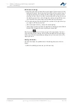
a) Distribute a small amount of not highly volatile flux on the residual soldering
points.
b) Remove any residual solder with a suitable tool.
ð
using, for instance, the Ersa soldering i-Tool bit, e.g. with the following sol-
dering tips:
PowerWell 0102WDLF23/SB (small), 0102ADLF40/SB (medium) or
0102ZDLF150/SB (large)
c) Remove flux residue with Ersa Flux Remover (0FR200).
d) Dry the solder joints with a clean, lint-free cloth.
Ersa GmbH
Operating_instructions HR 500 DE 3BA00246-01 | Rev. 1
108 / 124
Содержание HR 500
Страница 2: ......
Страница 6: ......
Страница 20: ...2 Technical data PC system requirements Ersa GmbH Operating_instructions HR 500 DE 3BA00246 01 Rev 1 20 124 ...


