speed (the corresponding pilot lamp comes on); when
pressing the button a second time (while the pilot lamp is
on) , the TIMER is activated and thus the motor stops after
5’ (the pilot lamp flashes). Button E: drives the motor in
fourth speed (the corresponding pilot lamp comes on);
when pressing the button a second time (while the pilot
lamp is on) , the TIMER is activated and thus the motor
stops after 5’ (the pilot lamp flashes).
Pay special attention to the grease filters: if the
model purchased has the controls shown in Figure 15: the
grease filters must be cleaned approximately once every
30 hours of operation (when the central segment on the
display goes on or starts blinking). To remove the filters:
press inward on the clamps at the handles and pull the
filter downward. Wash out the filter using a neutral soap.
Once the cleaned filters are reinstalled, keep button R
(Reset) pressed for two seconds to reset the counter. For
further information, see the Controls in Fig. 15 in the
paragraph entitled “Operation”. If the model purchased
has the controls shown in Figure 16/17/18: the grease
filter must be cleaned periodically: exactly how often
depends on use (at least once every other month). To
remove the filter: push inward on the clamp at the handle
and pull the filter downward. Wash out the filter using a
neutral soap. If the model purchased has the controls
shown in Figure 19: the grease filters must be cleaned
approximately once every 30 hours of operation (when the
light button lamp comes on) - Fig. 19S). To remove the
filters: press inward on the clamps at the handles and pull
the filter downward. Wash out the filter using a neutral
soap. Once the cleaned filters are reinstalled, to reset the
counter hold the light button pressed down for about 1”
(Fig.19A) while the corresponding pilot lamp (S) is on. For
further information, see the Controls in Fig.19 in the
paragraph entitled “Operation”.
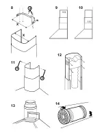
Replacing the charcoal filters: for filtering hoods,
the charcoal filters must be replaced; remove the filter with
a twisting movement (Fig. 14). If the model purchased has
the controls shown in Figure 15, the charcoal filters must
be replaced whenever the central segment of the display
starts blinking (i.e. every 120 hours of operation). If the
model purchased has the controls shown in Figure 16/17/
18, the charcoal filters must be replaced according to use:
on the average once every 6 months. If the model
purchased has the controls shown in Figure 19, the charcoal
filters must be replaced each time the light button (Fig.19S)
lamp flashes (i.e. every 120 hours of operation).
Lighting: Depending on the model purchased, see
Fig. 20, Fig.21 or Fig. 22.
Fig.20: to remove the halogen lamps, turn the locknut
counter-clockwise. Replace with the same type of lamp.
Fig. 21: to replace the incandescent light bulbs, remove
the grease filters so as to be able to access the inside of
the unit; remove the screw securing the light fitting and
then, working from inside the hood, push the light fitting pin
towards the inside of the unit. Replace with light bulbs of
the same type.
Fig. 22: if your appliance has the same kind of lights as in
the figure 21, to replace the incandescent light bulbs open
the grease filter and remove it; replace with light bulbs of
the same type.
ATTENTION
----------------------------------------------------
La distance minimum entre la surface de support des
casseroles sur le plan de cuisson et la partie inférieure
de la hotte doit être de 65 cm. Si les consignes, pour
l’installation du plan de cuisson, indiquent une plus
grande distance, il faut en tenir compte.
L'air aspiré ne doit pas être canalisé dans un conduit
qui est utilisé pour évacuer les fumées produites par
des appareils alimentés par des sources d'énergies
autres que l'énergie électrique (installations de
chauffage central, radiateurs, chauffe-eau, etc.).
Pour évacuer l'air qui doit être éliminé respectez les
prescriptions des autorités compétentes. De plus l'air
qui doit être évacué ne doit pas être déchargé dans
une cavité du mur, à moins que cette cavité soit
prévue pour ce but.
Prévoyez une aération de la pièce adéquate quand
une hotte et des appareils alimentés par une énergie
autre que l'énergie électrique (poêle à gaz, à huile, à
charbon etc.) sont utilisés en même temps. En effet,
en évacuant l'air, la hotte pourrait créer une dépression
dans la pièce. La pression négative de la pièce ne doit
pas dépasser 0,04mbar, évitant ainsi que la source
de chaleur provoque un appel des gaz qui doivent être
évacués. Il est donc nécessaire d'équiper la pièce de
prises d'air alimentant un flux d'air frais constant.
Contrôler la plaque des caractéristiques tech-
niques se trouvant à l’intérieur de l’appareil; si le
symbole (
) figure sur la plaque suivre les
instructions suivantes: cet appareil est construit
pour appartenir à la classe d’isolation II ; il ne doit
donc pas être relié à la terre.
Contrôler la plaque des caractéristiques
techniques se trouvant à l’intérieur de l’appareil;
si le symbole (
) NE figure pas sur la plaque
suivre les instructions suivantes: ATTENTION:
cet appareil doit être relié à la terre. Lors du
raccordement électrique s’assurer que la prise de
courant est équipée d’une connexion de mise à la
terre.
Lors du raccordement électrique assurez-vous que
les valeurs de tension correspondent à celles qui sont
indiquées sur la plaque des caractéristiques de
l’appareil, qui se trouve à l'intérieur de celui-ci. Si votre
appareil, n'a pas de câble flexible qui ne peut pas être
séparé ni de prise, ou bien d'autre dispositif qui
garantisse le débranchement de tous les pôles du
réseau, avec une distance d'ouverture entre les
contacts d'au moins 3 mm, ces dispositifs de séparation
du réseau doivent alors être prévus dans l'installation
fixe. Si votre appareil est muni d’un câble
d’alimentation, positionner l’appareil de manière à ce
Français
Содержание KD935.2
Страница 5: ...1 2 3 4 A 5A C D ...
Страница 6: ...6 B V M 5B C D A 7 B ...
Страница 7: ...8 X X W A 9 10 11 G 12 13 14 G ...
Страница 8: ...15 A B D R C 16 A B C 17 18 B C A A B C D E 20 22 21 A B D E C S 19 ...


