background image

41

HYDRAULIC UNIT

HYDRAULIC UNIT

The standard tractor has following hydraulic control
systems as shown below. Therefore, use the most
appropriate system for the implement you are using.

C

3-Point Hitch Control System

1. Position Control
2. Draft Control
3. Mixed Control
4. Float Control

C

Remote Hydraulic Control System

A

Do not operate until the engine is warmed up. If
operation is attempted when the engine is still cold, the
hydraulic system may be damaged.

A

If noises are heard when implement is lifting after the
hydraulic control lever has been activated, the
hydraulic mechanism is not adjusted properly. Unless
corrected, the unit will be damaged. Contact your
KUBOTA Dealer for adjustment.

3-POINT HITCH CONTROL SYSTEM

B

Position Control

This will control the working depth of 3-point hitch
mounted implement regardless of the amount of pull
required.

B

Draft Control

This will control the pull of the 3-point implement. As the
load on the 3-point hitch changes due to various soil
conditions, the draft control system automatically
responds to these changes by either raising or lowering
the implement slightly to maintain a constant pull.
Place the position control lever in the lowest position and
set the implement pull with the draft control lever.

B

Mixed Control

In draft control, when draft decreases, the implement
automatically lowers to increase draft. However, the
implement sometimes lowers too much. To limit the
degree, the implement can be lowered, set the position
control lever at the lowest working depth desired for the
implement. Lower the draft control lever to the point where
the implement is at the desired depth. 
This stops the implement from going too deep and
causing loss of traction and ground speed.

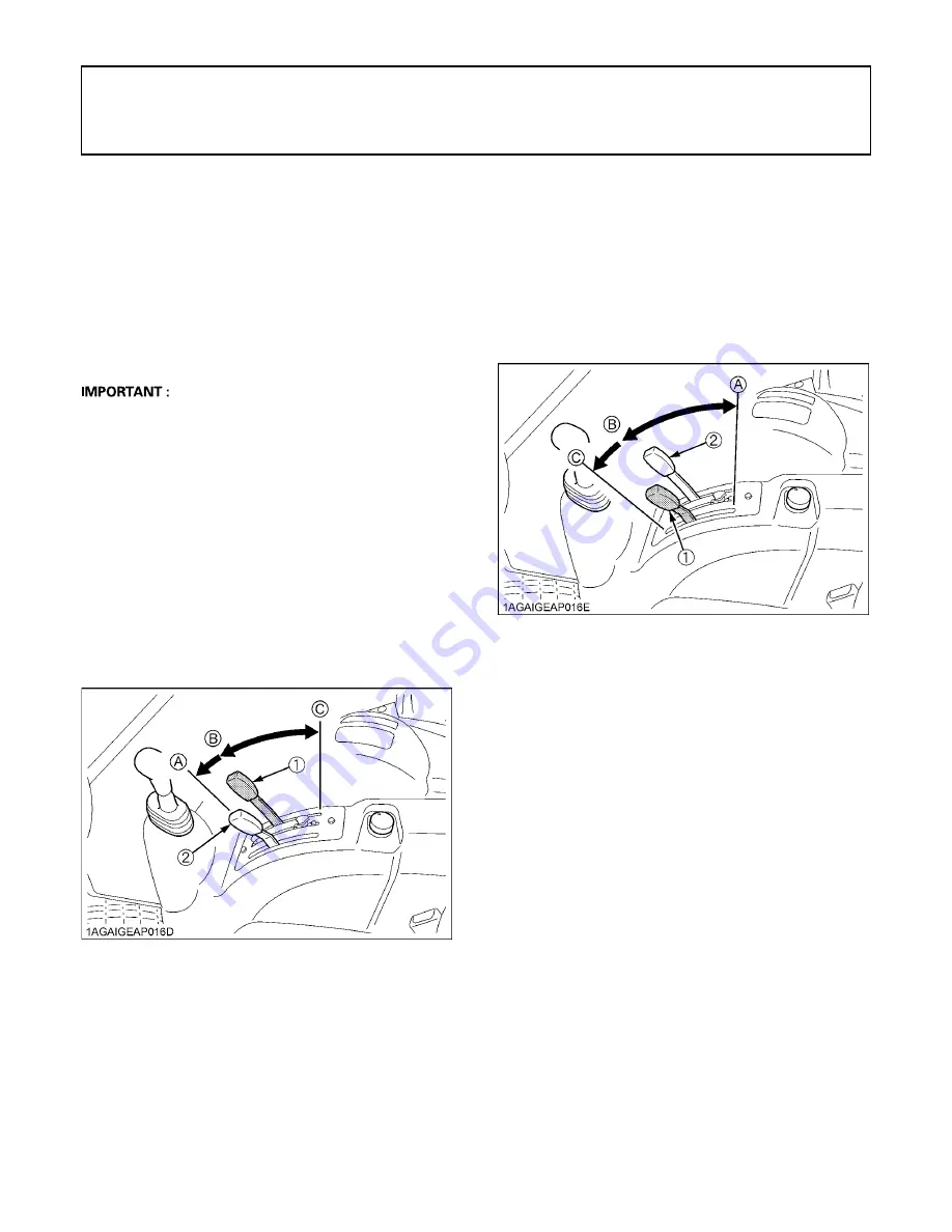
(1) Position control lever
(2) Draft control leve

r

(A) "FLOAT"
(B) "DOWN

"

(C) "UP"

(1) Draft control lever
(2) Position control lever

(A) "SENSITIVE"
(B) "INSENSITIVE"
(C) "FLOAT"

Содержание Power Krawler M8540 NARROW

Страница 1: ...PRINTED IN JAPAN English Australia Code No 3C873 9971 1 M 8 5 4 0 N TRACTOR OPERATOR S MANUAL MODEL M8540 NARROW KUBOTA Corporation 2009...

Страница 2: ...y food from the soil and from the sea industrial development architecture and construction and transportation Thousands of people depend on KUBOTA s know how technology experience and customer service...

Страница 3: ...froster N Steering Wheel Tilt Control Empty Full i PTO 540 rpm 540 i PTO 1000 rpm 1000 Beacon Light 3 Safety Alert Symbol R Diesel Fuel T Fuel Level b Engine Rotational Speed h Hourmeter Elapsed Opera...

Страница 4: ...will have the most up to date information Please do not hesitate to consult with them 3 SAFETY FIRST This symbol the industry s Safety Alert Symbol is used throughout this manual and on labels on the...

Страница 5: ...TING THE TRACTOR 17 OPERATING NEW TRACTOR 17 Do not Operate the Tractor at Full Speed for the First 50 Hours 17 Changing Lubricating Oil for New Tractors 17 STARTING 17 Operator s Seat 17 Seat Belt 18...

Страница 6: ...Gear Shift Lever 35 LCD Monitor Message 35 PTO Shaft Cover and Shaft Cap 35 THREE POINT HITCH DRAWBAR 36 3 POINT HITCH 37 Category 1 2 37 Selecting the holes of Lower Links 37 Selecting the Top Link...

Страница 7: ...Control Vent 50 Control Panel 51 Operation 52 REAR SIDE DEFOGGER WITH TIMER if equipped 54 INSTALLING THE IMPLEMENT CONTROL BOX 54 ELECTRICAL OUTLET 54 Electrical Outlet 54 BEACON LIGHT 55 Beacon Lig...

Страница 8: ...ng Fresh Air Filter 75 Checking Air Conditioner Condenser 75 Adjusting Air Conditioner Belt Tension 76 EVERY 300 HOURS 76 Changing Engine Oil 76 Replacing Hydraulic Oil Filter 77 EVERY 400 HOURS 78 Re...

Страница 9: ...g Lift Cylinder Hose 83 Replacing Air Conditioner Hose 83 SERVICE AS REQUIRED 83 Bleeding Fuel System 83 Bleeding Brake System 84 Draining Clutch Housing Water 84 Replacing Fuse 84 Replacing Slow Blow...

Страница 10: ......

Страница 11: ...build up may contribute to fires and lead to personal injury 9 Use only implements meeting the specifications listed under IMPLEMENT LIMITATIONS in this manual or implements approved by KUBOTA 10 Use...

Страница 12: ...hat are missing or damaged 5 Avoid sudden starts To avoid upsets slow down when turning on uneven ground and before stopping 6 The tractor cannot turn with the differential locked and attempting to do...

Страница 13: ...ad as shown in TIRE WHEEL AND BALLAST section Follow recommendations for proper ballasting 6 To avoid free wheeling A Do not shift the shuttle lever while on a slope A Stop completely by using the bra...

Страница 14: ...f the tractor connecting disconnecting adjusting cleaning or servicing any PTO driven equipment 2 Keep the PTO shaft cover in place at all times Replace the PTO shaft cap when the shaft is not in use...

Страница 15: ...s below the LOWER lower limit level mark Check the fluid level regularly and add distilled water as required so that the fluid level is between the UPPER and LOWER levels 9 To avoid sparks from an acc...

Страница 16: ...for suspected leaks use a piece of cardboard or wood Use of safety goggles or other eye protection is also highly recommended If injured by escaping fluid see a medical doctor at once This fluid will...

Страница 17: ...nded to alert persons to potential hazards The hazard is identified by a pictorial in the safety alert triangle or by the safety alert symbol alone An adjacent pictorial provides instructions and info...

Страница 18: ...SAFE OPERATION 8...

Страница 19: ...ing pictorial safety labels with new labels from your local KUBOTA Dealer 4 If a component with pictorial safety label s affixed is replaced with new part make sure new label s is are attached in the...

Страница 20: ......

Страница 21: ...e your KUBOTA Dealer For service contact the KUBOTA Dealership from which you purchased your tractor or your local KUBOTA Dealer When in need of parts be prepared to give your dealer the tractor CAB R...

Страница 22: ...acity 12V RC 160 min CCA 900A Fuel tank capacity L 76 Engine oil capacity L 10 7 Coolant capacity L 9 0 Dimensions Overall length with 3P mm 3620 Overall width minimum tread mm 1486 Overall height mm...

Страница 23: ...nks horizontal 24 in behind lifting point kg 1500 Remote hydraulic control 2 standard 3rd valve optional System pressure MPa kgf cm 19 1 195 Traction system Swinging drawbar adjustable in direction PT...

Страница 24: ...lever Main gear shift lever km h CREEP 1 0 38 2 0 55 3 0 71 4 0 90 5 1 19 L 1 2 7 2 3 8 3 4 9 4 6 3 5 8 4 H 1 10 9 2 15 4 3 19 8 4 25 3 5 33 4 CREEP 1 0 36 2 0 52 3 0 67 4 0 86 5 1 13 L 1 2 6 2 3 7 3...

Страница 25: ...or failures of the tractor resulting from use with improper implements are not covered by the warranty A Implement size may vary depending on soil operating conditions Tread max width Lower link end...

Страница 26: ...dth mm 2130 3 Sprayer Max Tank Capacity Mid L 680 Rear 3P L 680 Drawbar L 4000 4 Rotary Tiller Max Tilling Width mm 2130 Max Weight kg 800 5 Bottom Plow Max Size 14 in x 3 16 in x 2 18 in x 1 Max Weig...

Страница 27: ...1 Horn button 20 2 Parking brake lever 24 3 Hydraulic shuttle shift lever 22 4 Clutch pedal 21 5 Tilt pedal 18 6 Easy Checker TM 25 7 Hand throttle lever 24 8 Turn signal Head light switch 19 19 9 Bea...

Страница 28: ...tor 25 3 Trailer indicator 19 13 Parking brake indicator 24 4 PTO clutch indicator 34 14 Fuel level indicator 25 5 Liquid crystal display 27 15 Fuel gauge 26 6 Electrical charge indicator 25 16 Coolan...

Страница 29: ...er 22 5 Operator s seat 17 6 Seat belt 18 7 Main gear shift lever 22 8 Remote control valve lever 42 9 Position control lever 41 10 Draft control lever 41 11 PTO clutch control switch 34 12 Electrical...

Страница 30: ...10 INSTRUMENT PANEL AND CONTROLS ILLUSTRATED CONTENTS 1 Trailer electrical outlet 33 2 PTO gear shift lever 35 3 Remote control valve coupler 43...

Страница 31: ...heck item Walk around inspection Check engine oil level Check transmission oil level Check coolant level Check washer liquid level Check water separator Clean grill and radiator screen Clean air condi...

Страница 32: ...O clutch control switch in OFF position before starting the engine A Do not use starting fluid or ether A To protect the battery and the starter make sure that the starter is not continuously turned f...

Страница 33: ...ch 2 Position control lever 3 Draft control lever ON OFF A DOWN 5 Set the throttle lever to about 1 2 way 1 Hand throttle lever 2 Foot throttle INCREASE DECREASE 6 Insert the key into the key switch a...

Страница 34: ...ttle shift lever is placed in the NEUTRAL position If a lamp is still on immediately stop the engine and determine the cause COLD WEATHER STARTING If the ambient temperature is below 0 and the engine...

Страница 35: ...start engine A Do not connect other end of negative jumper cable to negative terminal of tractor battery When jump starting engine follow the instructions below to safely start the engine 1 Bring hel...

Страница 36: ...only matching voltage source when Jump starting a low or dead battery condition A Do not operate the tractor with the battery cable disconnected from the battery A Do not operate the tractor without...

Страница 37: ...ally observed in the case of new tractors BChanging Lubricating Oil for New Tractors The lubricating oil is especially important in the case of a new tractor The various parts are not broken in and ar...

Страница 38: ...will cause burning A Remove all weeds straw and combustible material from the muffler pipe muffler and exhaust manifold to prevent fires If necessary loosen the nut and adjust the muffler pipe to the...

Страница 39: ...ts and indicator on the instrument panel will flash A The hazard light switch is operative when the key switch is in the ON ACC or OFF position A The turn signal light switch is only operative when th...

Страница 40: ...different between two and four wheel drive Be aware of the difference and use carefully 1 Before operating the tractor on the road be sure to interlock the right and left pedals as illustrated below 2...

Страница 41: ...dal is fully pressed down To help prevent premature clutch wear A The clutch pedal must be quickly disengaged and be slowly engaged A Avoid operating the tractor with your foot resting on the clutch p...

Страница 42: ...the tractor is completely stopped and the clutch is depressed A To avoid transmission damage depress clutch pedal and stop the tractor before shifting between ranges BHydraulic Shuttle Shift Lever Ra...

Страница 43: ...at road speed A When driving on icy wet or loose surfaces make sure the tractor is correctly ballasted to avoid skidding and loss of steering control Operate at reduced speed and engage front wheel d...

Страница 44: ...d of rows planting cultivating harrowing 2 Increasing maneuverability when working in tight spaces A Tires will wear quickly if the front wheel drive is engaged on paved roads BHand Throttle Lever Pul...

Страница 45: ...f the oil pressure in the engine goes below the prescribed level the warning lamp in the Easy Checker TM will come on If this should happen during operation and it does not go off when the engine is a...

Страница 46: ...not remove radiator cap until coolant temperature is well below its boiling point Then loosen cap slightly to the stop to relieve any pressure before removing cap completely 1 With the key switch at O...

Страница 47: ...to the changing display 2 To switch between mph and km h for the traveling speed use the Traveling speed select switch 3 The PTO clutch control switch works for the following automatic display modes 1...

Страница 48: ...ayed A When the PTO clutch control switch is in OFF position OFF is displayed A See PTO Speed Display Mode Switching in PTO RPM TRAVEL SPEED MONITOR in OPERATING THE TRACTOR section 2 Display mode swi...

Страница 49: ...540E rpm model The PTO speed display mode has been factory set at Code 1 Do not attempt to change the code Otherwise the correct PTO speed will not be displayed in the LCD monitor NOTE The current co...

Страница 50: ...ameter tires are fitted on the machine the travel speed display mode must be changed Otherwise the travel speed will not get correctly displayed Such mode switching is also needed when the original ti...

Страница 51: ...To avoid personal injury due to loss of steering control A Do not operate the tractor at high speed with differential lock engaged A Do not attempt to turn with the differential lock engaged A Be sure...

Страница 52: ...actor close to the edges of ditches or banks which may collapse under the weight of the tractor Especially when the ground is loose or wet 1 Be sure wheel tread is adjusted to provide maximum stabilit...

Страница 53: ...pplied for use with trailer or implement C Function of each terminals in trailer electrical outlet 1 Trailer electrical outlet Terminal Function 1 Turn signal light LH 2 3 Ground 4 Turn signal light R...

Страница 54: ...ease your hand In the ON position switch slightly rises itself To Turn OFF Tap on top of the switch and the switch will return to the OFF position A To avoid shock loads to the PTO reduce engine speed...

Страница 55: ...th the PTO clutch control switch set to OFF A When light load select the 540E position for economical operation BLCD Monitor Message 1 The PTO rpm can be checked in the LCD monitor See PTO RPM TRAVEL...

Страница 56: ...36 THREE POINT HITCH DRAWBAR THREE POINT HITCH DRAWBAR 1 Top link 2 Lifting rod Left 3 Telescopic stabilizers 4 Lower link 5 Lifting rod Right 6 Drawbar...

Страница 57: ...e B hole A The lifting rods may be attached to A for greater lifting force BSelecting the Top Link Mounting Holes Select the proper set of holes by referring to the Hydraulic Control Unit Use Referenc...

Страница 58: ...equipment may fall BLifting Rod Left By turning the rod itself the lifting rod varies its length When extending the rod do not exceed the groove on the rod thread BLifting Rod Right To avoid personal...

Страница 59: ...y of the implement Select the proper set of holes by referring to the Hydraulic Control Unit Use Reference Chart in REMOTE HYDRAULIC CONTROL SYSTEM in HYDRAULIC UNIT section After aligning satisfactor...

Страница 60: ...Doing so could cause the tractor to tip over rearward causing personal injury or death A The drawbar load is referred to IMPLEMENT LIMITATIONS section BSwing Drawbar The drawbar can be used in three d...

Страница 61: ...t of pull required BDraft Control This will control the pull of the 3 point implement As the load on the 3 point hitch changes due to various soil conditions the draft control system automatically res...

Страница 62: ...le segments It is not possible to use triple segments with flow control valve BRemote Control Valve The standard tractor is equipped with double acting valve A Double acting valve with detents and sel...

Страница 63: ...elieve pressure before connecting or disconnecting lines A Do not use your hand to check for leaks C Connecting 1 Clean both couplers 2 Remove dust plugs 3 Insert the implement coupler to the tractor...

Страница 64: ...table position and set the implement pull with the position control lever YES NO Loose Inserttheset pin through the slot on the outer tube that align with one of the holes on the inner bar For impleme...

Страница 65: ...y set to the prescribed level it naturally drops slowly in the course of time Thus check it everyday and inflate as necessary A Maintain the maximum pressure in front tires if using a front loader or...

Страница 66: ...f weights or consult your local KUBOTA Dealer to use A Do not overload tires A Add no more weight than indicated in chart A Do not attach the front bumper when the front loader is attached BRear Balla...

Страница 67: ...clockwise to unlock the door To lock the door turn the key in the opposite direction The key can be removed when it is in the vertical direction From the inside Push down the lock knob to lock the doo...

Страница 68: ...onfuse operators of oncoming vehicles BWork Light Switch Turn on the key switch and press the top half of the work light switch The work light and the switch s indicator light up Press the bottom half...

Страница 69: ...activated continuously 2 Press the bottom half of the wiper washer switch washer liquid only jets out A Do not activate the wipers when the windows are dry they may be scratched Be sure to jet washer...

Страница 70: ...rotate the outlets toward the windshield C Side air outlet and door air outlet The side and door air outlets can be adjusted to direct air on to the operator door window or the rear of the CAB A If t...

Страница 71: ...de switch to the desired position C Temperature Control Dial Set this dial at the desired position to obtain the optimum air temperature Turn the dial in the WARM direction to obtain warmer air Turn i...

Страница 72: ...he blower 1 2 3 switch and the temperature control dial to achieve a comfortable temperature level C Cooling or dehumidifying heating 1 Set the mode switch to the position 2 Set the recirculation fres...

Страница 73: ...l and your feet warm C Defrosting or demisting To defrost or demist the windshield take the following steps 1 Set the mode switch to the position 2 Open the front air outlet and direct it to the winds...

Страница 74: ...the ON or ACC positions with the engine stopped Always use the defogger with the engine running INSTALLING THE IMPLEMENT CONTROL BOX 1 Make an opening in each of the corner plugs Introduce the impleme...

Страница 75: ...switch s indicator light up Press the switch to turn off the light and indicator A The relay harness for beacon light is in the accessories box A Pre assemble the beacon light and relay harness and c...

Страница 76: ...lement Clean every 100 Hr 68 1 Replace every 1 year 81 2 Secondary element Replace every 1 year 81 8 Fuel line Check every 100 Hr 69 Replace every 2 years 83 4 9 Parking brake Check every 100 Hr 70 10...

Страница 77: ...8 Intake air heater Check every 3000 Hr 80 4 29 Cooling system Flush every 2 years 81 30 Coolant Change every 2 years 81 31 Master cylinder filter Clean every 2 years 82 4 32 Lift cylinder hose Replac...

Страница 78: ...k the battery condition by reading the indicator annually No Items Indication on hour meter Interval Ref page 50 100 150 200 250 300 350 400 450 500 550 600 650 700 1 Inner air filter Clean every 200...

Страница 79: ...ation CF or CI 4 External EGR type engine Above 25 SAE30 SAE10W 30 or 15W 40 0 to 25 SAE20 SAE10W 30 or 15W 40 Below 0 SAE10W SAE10W 30 or 15W 40 5 Transmission case 52 L KUBOTA UDT or SUPER UDT fluid...

Страница 80: ...the transmission is also used as hydraulic fluid To insure proper operation of the hydraulic system and to complete lubrication of the transmission it is important that a multi grade transmission flu...

Страница 81: ...rns could result A Hold the hood with other hand while unlocking release lever BHood To open the hood hold the hood and pull the release lever and open the hood A To close the hood push the hood into...

Страница 82: ...the white line close the fuel cock loosen the retainer ring take out the cup and clean the cup Be careful not to break the element 3 Place the cup back into position Bleed the fuel system See SERVICE...

Страница 83: ...efore removing the cap completely 1 Check to see that the coolant level is between the FULL and LOW marks of recovery tank 2 When the coolant level drops due to evaporation add soft water only up to t...

Страница 84: ...ars the hole and take out the panel 2 Attaching the panel is performed vice versa C Sliding the air conditioner condenser 1 Release the air conditioner hoses off the hook 2 Loosen the wing nut 3 Hold...

Страница 85: ...pedals for free travel and smooth operation 2 Adjust if incorrect measurement is found See Adjusting Brake Pedal in EVERY 100 HOURS in PERIODIC SERVICE section BChecking Parking Brake Pull the parkin...

Страница 86: ...the key to START position 7 The engine must not crank 8 If it cranks consult your local KUBOTA Dealer for this service C Test Checking Operator Presence Control O P C System 1 Follow the instruction...

Страница 87: ...larly especially when new If they are loose tighten them as follows EVERY 100 HOURS BLubricating Grease Fittings Apply a small amount of multipurpose grease to the following points every 100 hours If...

Страница 88: ...t several times in water rinse with clean water and dry it naturally After element is fully dried inspect inside of the element with a light and check if it is damaged or not 3 Replace air cleaner pri...

Страница 89: ...top the engine before checking belt tension 1 Stop the engine and remove the key 2 Apply moderate thumb pressure to belt between pulleys 3 If tension is incorrect loosen the alternator mounting bolts...

Страница 90: ...Checking the equalizer working level anti imbalance device 1 Gently step on both brake pedals at once 2 Further step on the right hand pedal the left hand pedal slightly raises itself and measure the...

Страница 91: ...original battery is maintenance free but needs some servicing If the battery is weak the engine will be difficult to start and the lights will be dim It is important to check the battery periodically...

Страница 92: ...three months in hot seasons and once every six months in cold seasons EVERY 200 HOURS BChecking Radiator Hose and Clamp Check to see if radiator hoses are properly fixed every 200 hours of operation...

Страница 93: ...wheel so front wheels are in the straight ahead position 3 Lower the implement lock the park brake and stop the engine 4 Measure distance between tire beads at front of tire at hub height 5 Measure d...

Страница 94: ...ctor after a long period of storage BCleaning Inner Air Filter Remove the inner filter and blow air from the direction opposite to the filter s normal air flow Pressure of compressed air must be under...

Страница 95: ...ter and let it air dry A Do not use gasoline thinner or similar chemicals to clean the filter as damage to the filter may occur A It may also cause an unpleasant odor in the CAB when the system is use...

Страница 96: ...avoid personal injury A Be sure to stop the engine before changing the oil A Allow engine to cool down sufficiently oil can be hot and can burn 1 To drain the used oil remove the drain plug at the bot...

Страница 97: ...until it contacts the mounting surface Tighten filter by hand an additional 1 2 turn only 7 After the new filters have been replaced fill the transmission oil up to the upper notch on the dipstick 8...

Страница 98: ...the element and dip it in the kerosene to rinse 4 After cleaning reassemble the water separator keeping out dust and dirt 5 Bleed the fuel system See Bleeding Fuel System in SERVICE AS REQUIRED in PER...

Страница 99: ...inutes stop it and check the oil level again add oil to prescribed level A Do not operate the tractor immediately after changing the transmission fluid Run the engine at medium speed for a few minutes...

Страница 100: ...e Valve Clearance Consult your local KUBOTA Dealer for this service EVERY 1500 HOURS BChecking Fuel Injection Nozzle Injection Pressure Consult your local KUBOTA Dealer for this service EVERY 3000 HOU...

Страница 101: ...ol down 2 To drain the coolant open the radiator drain plug remove the drain plug and remove radiator cap The radiator cap must be removed to completely drain the coolant 3 After all coolant is draine...

Страница 102: ...ain Repeat this procedure 2 or 3 times to clean up the inside 3 Mixing the LLC Put the LLC in cooling water in the percentage for a target temperature When mixing stir it up well and then fill into th...

Страница 103: ...d 2 When water is drained from water separator 3 When tank is completely empty 4 After the tractor has not been used for a long period of time C Bleeding procedure is as follows 1 Fill the fuel tank w...

Страница 104: ...actor has been washed water may get into the clutch housing Remove the drain plug and drain the water then install the plug again BReplacing Fuse The tractor electrical system is protected from potent...

Страница 105: ...e Window Defogger 2 20 Rear Window Defogger 3 10 4WD Bi Speed Turn 4 10 4WD brake 5 15 Work Light Rear 6 15 Work Light Front 7 15 Cigarette Lighter 8 20 Air Conditioner Fan Motor 9 10 Air Conditioner...

Страница 106: ...p assembly in the reverse order A Be sure to use a new bulb of the specified wattage A Never touch the bulb surface glass with bare hands Fingerprints for example may break the bulb BLubricating Point...

Страница 107: ...TA Dealer for assistance and service A shortage of refrigerant impairs the air conditioner performance Check the following points If it is indicated that the amount of refrigerant is extremely low ask...

Страница 108: ...Y 100 HOURS in PERIODIC SERVICE section 9 Keep the tractor in a dry place where the tractor is sheltered from the elements Cover the tractor 10 Store the tractor indoors in a dry area that is protecte...

Страница 109: ...air heater system trouble A Check to see if the slow blow fuse of the intake air heater blows A Check to see if the intake air heater functions in cold weather Insufficient engine power A Insufficient...

Страница 110: ...A Front end weights For front ballast A Rear Wheel Weights For rear ballast A Double Acting Remote Hydraulic Control Valve with Detents and Self Cancelling A Double Acting Remote Hydraulic Control Val...

Отзывы: