2. Remote control valve lever
The remote control valve lever directs pressurized oil
flow to the implement hydraulic system.
Example: Installing fifth segment valves
Standard
valves
1st
Double acting valve with detents and self
canceling
2nd
Double acting valve with detents and self
canceling
Optional
valves
(selectable
configura-
tion)
3rd
Double acting valve with float position
4th
Double acting valve with float position
5th
Single or double acting valve
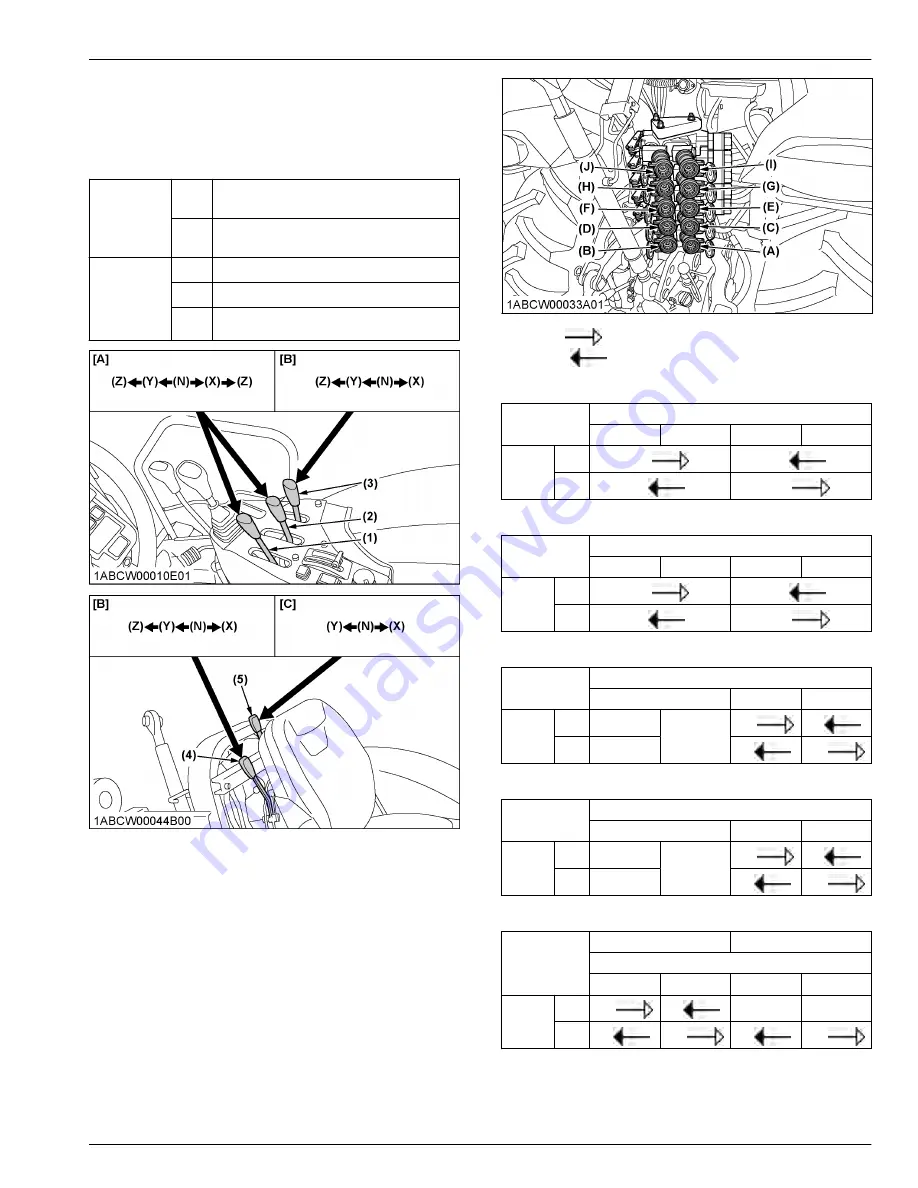
(1) Remote control valve lever 1
(standard)
(2) Remote control valve lever 2
(standard)
(3) Remote control valve lever 3
(option)
(4) Remote control valve lever 4
(option)
(5) Remote control valve lever 5
(option)
[A] Double acting valve with de-
tents and self canceling
[B] Double acting valve with
float position
[C] Single or double acting valve
Pressure
Returning
Double acting valve with detents and self canceling
Lever 1
Lever position
Z (detent)
Y
X
Z (detent)
Port
(A)
out
in
(B)
in
out
Double acting valve with detents and self canceling
Lever 2
Lever position
Z (detent)
Y
X
Z (detent)
Port
(C)
out
in
(D)
in
out
Double acting valve with float position
Lever 3
Lever position
Z (detent)
Y
X
Port
(E)
in
Float
out
in
(F)
out
in
out
Double acting valve with float position
Lever 4
Lever position
Z (detent)
Y
X
Port
(G)
in
Float
out
in
(H)
out
in
out
Single or double acting valve
Lever 5
Double-acting
Single-acting
Lever position
Y
X
Y
X
Port
(I)
out
in
-
-
(J)
in
out
in
out
IMPORTANT :
• Do not hold the lever in the “Pull” or “Push”
position once the remote cylinder has reached
REMOTE HYDRAULIC CONTROL SYSTEM
HYDRAULIC UNIT
M4N-071, M5N-091, M5N-111
83
Содержание M4N-071
Страница 5: ......
Страница 6: ......
Страница 21: ...SAFETY LABELS SAFE OPERATION M4N 071 M5N 091 M5N 111 15...
Страница 22: ...SAFE OPERATION 16 M4N 071 M5N 091 M5N 111...
Страница 23: ...SAFE OPERATION M4N 071 M5N 091 M5N 111 17...
Страница 24: ...SAFE OPERATION 18 M4N 071 M5N 091 M5N 111...
Страница 26: ...20 M4N 071 M5N 091 M5N 111...
Страница 152: ......


