SYNTEX
®
-NC
Operating/Assembly instructions
KTR-N
Sheet:
Edition:
46110 EN
23 of 23
4
Please observe protection
note ISO 16016.
Drawn:
2017-02-10 Pz/Koh
Replacing:
KTR-N dated 2014-08-11
Verified:
2017-03-03 Pz
Replaced by:
Insert the drive element such as belt pulleys or gear wheels with the
centering (H7 fit) on the deep groove ball bearing (component 1.7 or
2.7).
Design the deep groove ball bearing as a fixed bearing.
Screw the drive component to the flange ring (component 1.2 or
2.2).
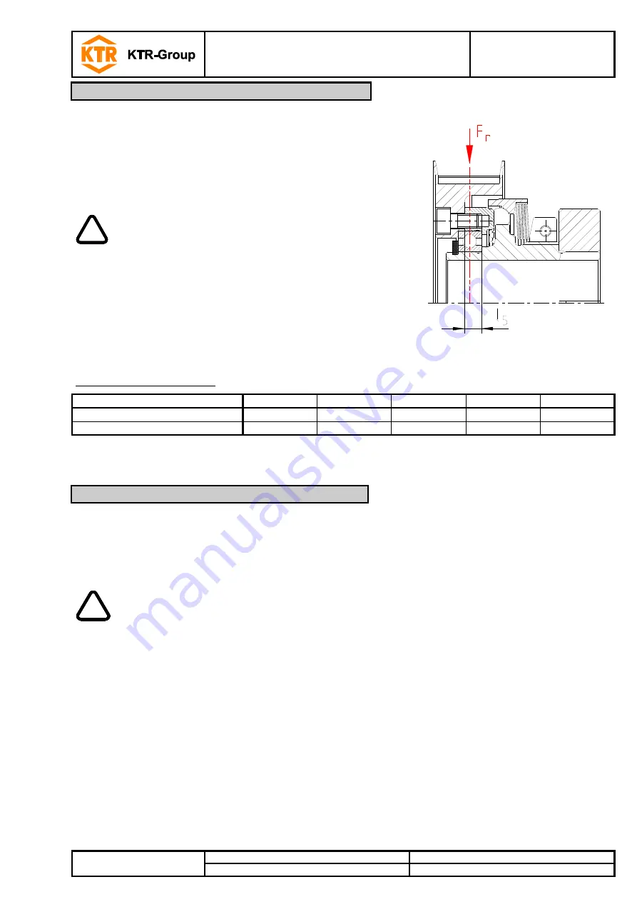
Illustration 22
!
With the asssembly the maximum depth of
engagement l
5
(see table 1, illustration 22) needs to
be observed.
The customer needs to select the screw connection
for transmitting the torque.
The pitch line of radial forces F
r
arising has to lead
through the center of the bearing (see illustration 22).
The radial and axial forces passed into the coupling
bearing must not exceed the maximum permissible
figures (see table 11).
Table 11: Max. bearing load
Size
15
25
32
42
60
Axial force [N]
300
400
500
800
1200
Radial force [N]
300
400
500
800
1200
A basic requirement to ensure the readiness for use of the coupling is a stock of the most important spare parts
on site.
Contact addresses of the KTR partners for spare parts and orders can be obtained from the KTR homepage at
www.ktr.com.
!
KTR does not assume any liability or warranty for the use of spare parts and accessories
which are not provided by KTR and for the damages which may incur as a result.
10
Notes for using drive components/attachments
11
Spares inventory, customer service addresses


