background image


ROTEX

®

 SP "Non Sparking" 

Operating/Assembly instructions 

KTR-N 
Sheet: 
Edition: 

40228 EN 
3 of 28 


Please observe protection 

note ISO 16016. 

Drawn: 

2019-10-10 Pz/Bru 

Replacing: 

KTR-N dated 2017-01-02 

Verified: 

2019-10-10 Pz 

Replaced by: 


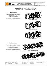
Illustration 1: Type GN (No. 080) - component 1, 1a, 1b: steel (St) 

Illustration 2: Type GN (No. 080) - component 1, 1a, 1b: cast iron (GJL) 


Table 1: Type GN (No. 080) - component 1, 1a, 1b: steel (St) 

Size 

Spider 

1)


(component 

2) 

Rated torque 

[Nm] 

Com-

po-

nent 

(St) 

Dimensions [mm] 

3)


Component 1, 1a, 1b steel (St) 

Com-

po-

nent 

Dimensions [mm] 

3)


Component 1c 

Max. 

finish 

bore d

1


2)


l

1


D

H


d

H


D, D

1


Max. 

finish 

bore d

2


2)


l

2


D

A


24 

35 

1a 

35 

78 

30 

18 

14 

2.0 

55 

27 

55 

1c 

28 

30 

61 

1b 

98 

50 

28 

95 

1a 

40 

90 

35 

20 

15 

2.5 

65 

30 

65 

1c 

32 

35 

72 

1b 

115 

60 

38 

190 

48 

114 

45 

24 

18 

3.0 

80 

38 

70 

27 

1c 

42 

45 

87 

1b 

139 

70 

80 

42 

265 

55 

126 

50 

26 

20 

3.0 

95 

46 

85 

28 

1c 

48 

50 

103 

1b 

151 

75 

995 

48 

310 

62 

140 

56 

28 

21 

3.5 

105 

51 

95 

32 

1c 

55 

56 

114 

1b 

164 

80 

105 

55 

410 

74 

160 

65 

30 

22 

4.0 

120 

60 

110 

37 

1c 

65 

65 

130 

1b 

185 

90 

120 

65 

625 

80 

185 

75 

35 

26 

4.5 

135 

68 

115 

47 

1c 

75 

75 

146 

1b 

210 

100 

135 


Table 2: Type GN (No. 080) - component 1, 1a, 1b: cast iron (GJL)


Size 

Spider 

1)


(component 

2) 

Rated torque 

[Nm] 

Com-

po-

nent 

(GJL) 

Dimensions [mm] 

3)


Component 1, 1a, 1b: cast iron (GJL) 

Com-

po-

nent 

Dimensions [mm] 

3)


Component 1c 

Max. 

finish 

bore d

1


2)


l

1


D

H


d

H


D, D

1


Max. 

finish 

bore d

2


2)


l

2


D

A


38 

190 

40 

114 

45 

24 

18 

3.0 

80 

38 

66 

37 

1c 

42 

45 

87 

1a 

48 

78 

1b 

139 

70 

62 

42 

265 

45 

126 

50 

26 

20 

3.0 

95 

46 

75 

40 

1c 

48 

50 

103 

1a 

55 

94 

1b 

151 

75 

65 

48 

310 

52 

140 

56 

28 

21 

3.5 

105 

51 

85 

45 

1c 

55 

56 

114 

1a 

62 

104 

1b 

164 

80 

69 

55 

410 

60 

160 

65 

30 

22 

4.0 

120 

60 

98 

52 

1c 

65 

65 

130 

1a 

74 

118 

65 

625 

70 

185 

75 

35 

26 

4.5 

135 

68 

115 

61 

1c 

75 

75 

146 

1)  Maximum torque of the coupling T

Kmax.

 = rated torque of the coupling T

K rated

 x 2 

2)  Bores H7 with keyway to DIN 6885 sheet 1 [JS9] and setscrew 
3)  Dimensions G and t see table 9. 


Technical data 

Содержание E4-DKM

Страница 1: ...rified 2019 10 10 Pz Replaced by ROTEX SP Non Sparking Single cardanic Torsionally flexible jaw couplings type GN GND EN and their combinations according to directive 2014 34 EU Type GN No 080 Type GN...

Страница 2: ...2 6 Reference to EC Machinery Directive 2006 42 EC 10 3 Storage transport and packaging 10 3 1 Storage 10 3 2 Transport and packaging 11 4 Assembly 11 4 1 Components of the couplings 11 4 2 Advice fo...

Страница 3: ...03 1b 151 75 995 48 310 1 62 140 56 28 21 3 5 105 51 95 32 1c 55 56 114 1b 164 80 105 55 410 1 74 160 65 30 22 4 0 120 60 110 37 1c 65 65 130 1b 185 90 120 65 625 1 80 185 75 35 26 4 5 135 68 115 47 1...

Страница 4: ...ted torque Nm Dimensions mm 3 Component 1c Max finish bore d1 2 L l1 l2 E b s DA dH a 24 35 28 78 30 18 14 2 0 61 27 4 28 95 32 90 35 20 15 2 5 72 30 38 190 42 114 45 24 18 3 0 87 38 42 265 48 126 50...

Страница 5: ...51 75 995 48 310 1 62 140 56 28 21 3 5 105 51 95 32 5c 40 60 36 114 1b 164 80 105 55 410 1 74 160 65 30 22 4 0 120 60 110 37 5c 45 66 40 130 1b 185 90 120 65 625 1 80 185 75 35 26 4 5 135 68 115 47 5c...

Страница 6: ...6 Max finish bore d2 2 l1 l2 l3 l4 DA a Ltotal DH dH l11 E b s 24 35 20 22 46 61 4 0 96 55 27 16 18 14 2 0 28 95 22 26 53 72 4 0 110 65 30 18 20 15 2 5 38 190 28 30 62 87 4 0 128 80 38 20 24 18 3 0 4...

Страница 7: ...5 62 55 140 410 70 240 65 50 30 22 4 0 120 110 130 60 37 M12 120 40 50 180 280 90 200 300 110 65 140 625 80 260 75 60 35 26 4 5 135 115 146 68 47 M12 120 48 40 180 300 80 1 Maximum torque of the coupl...

Страница 8: ...54 1 79 0 99 3 18 66 8 123 0 123 0 195 6 286 3 41 7 68 6 48 1 70 2 88 2 19 70 5 129 8 129 8 206 5 302 2 39 5 64 9 45 6 66 5 83 6 20 74 2 136 7 136 7 217 4 318 1 318 1 37 5 61 7 43 3 63 2 79 4 71 1 22...

Страница 9: ...ly injuries that may result in death Warning of product damages This symbol indicates notes which may contribute to preventing material or machine damage General advice This symbol indicates notes whi...

Страница 10: ...The transmittable torque of the shaft hub connection must be reviewed by the customer and is subject to his responsibility For drives subject to torsional vibrations drives with cyclic stress due to...

Страница 11: ...wise contractually agreed packaging will follow the in house packaging specifications of KTR The coupling is generally supplied in individual parts Before assembly the coupling has to be inspected for...

Страница 12: ...KM No 086 Component Quantity Description Illustration 12 Type E4 DKM No 086 2 2 Spider 92 ShA 3 2 Setscrews DIN EN ISO 4029 5bc 2 E4 hub SP 6 1 DKM spacer Components of ROTEX type ZS DKM C No 085 Comp...

Страница 13: ...a setscrew according to DIN EN ISO 4029 with a cup point or an end plate to fasten the hubs axially Only valid with type ZS DKM C Please provide for a setscrew or an end plate to fasten the hubs axial...

Страница 14: ...ns frequently alternating torsional direction shock loads etc The keyway should preferably be located between the cams With axial fastening by the setscrew the tapped hole should be located on the key...

Страница 15: ...ee table 9 If the shaft diameters with inserted feather key are smaller than dimension dH see table 1 to 5 of the spider one or two shaft ends may protude into the spider Illustration 15 Assembly of t...

Страница 16: ...ntil the hub bodies with the half shells fit closely to the shaft Shift the DH clamping hubs in axial direction until the dimension Ltotal is achieved see illustration 22 and table 7 Secure the DH cla...

Страница 17: ...e accurate the alignment of the coupling the longer is its service life If used in potentially explosive atmospheres for explosion group IIC only half of the displacement figures see table 12 to 14 ar...

Страница 18: ...1 0 1 0 1 1 0 75 0 85 1 10 1 40 1 60 2 00 2 30 Table 13 Displacement figures type E4 DKM No 086 Size 24 28 38 42 48 55 65 Max axial displacement Ka mm 1 4 1 5 1 8 2 0 2 1 2 2 2 6 1 0 1 4 1 4 2 0 2 0 2...

Страница 19: ...The coupling must not operate in an accumulation of dust For covers with unlocked openings on the top face no light metals must be used if the couplings are used as equipment of equipment group ll if...

Страница 20: ...sive atmospheres Elimination Different operating noise and or vibrations occuring Misalignment Increased temperature on the spider surface ignition risk by hot surfaces 1 Set the unit out of operation...

Страница 21: ...pling components and replace coupling components that have been damaged 4 Insert spider assemble coupling components 5 Inspect alignment adjust if necessary 6 Inspect and adjust ambient contact temper...

Страница 22: ...oupling fails Contact addresses of the KTR partners for spare parts and orders can be obtained from the KTR homepage at www ktr com KTR does not assume any liability or warranty for the use of spare p...

Страница 23: ...30 C to 75 C 95 C T6 30 C to 60 C 80 C Explanation The maximum surface temperatures each result from the maximum permissible ambient or operating temperature Ta plus the maximum temperature increase T...

Страница 24: ...according to the table Breakdowns if possible The maintenance intervals must be adjusted to the modified operating parameters without fail M2 2G 2D Gases and vapours of explosion group IIC The torsio...

Страница 25: ...cur an inspection must be made with the machine stopped Reaching the limits for replacing depends on the operating conditions and the existing operating parameters In order to ensure a long service li...

Страница 26: ...er without aluminium Category 3 hubs resp clamping hubs without feather keyway ROTEX Year I M2 Ex h I Mb II 3G Ex h IIC T6 T4 Gc II 3D Ex h IIIC T80 C T110 C Dc 30 C Ta 60 C 90 C KTR Systems GmbH Carl...

Страница 27: ...DKM C only Complete marking valid for PUR only II 2G c IIC T6 T5 resp T4 30 C Ta 65 C 80 C resp 90 C II 2D c T 110 C I M2 c 30 C Ta 90 C Substance group gases fogs and vapours The marking with explosi...

Страница 28: ...afety and health requirements according to enclosure II of directive 2014 34 EU The coupling described in here complies with the specifications of the following standards rules DIN EN ISO 80079 36 DIN...

Отзывы: