background image

30/ASSEMBLING THE ENGINE

133

600342-10

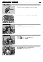
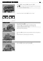
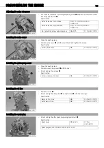
Mount the cylinder head. Mount screws


and tighten in a crisscross pattern.

Specification

Screw, cylinder head

M10

Step 1
40


Nm

(29.5


lbf


ft)

Step 2
50


Nm

(36.9


lbf


ft)

600343-10

Mount and tighten screws


.

Specification

Screw, cylinder head

M6

10


Nm (7.4


lbf


ft)

20.13

Installing the camshaft

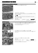
600346-10

Insert the camshaft. Drill hole


in the seal holder must face upward and autde-

compression stop


must be at the top.

600347-10

Align camshaft marking


with the cylinder head.

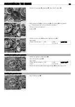
600348-10

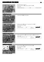
Place the timing chain over the camshaft gear and connect with a new rivet link.
Clamp tab


with the special tool.

Timing chain separating and riveting tool (59029020000) (

P. 209)

Содержание 2008 450 XC ATV

Страница 1: ...REPAIR MANUAL 2008 450 XC ATV 525 XC ATV ART NO 3206058en ...

Страница 2: ......

Страница 3: ...t to change or cancel technical speci fications prices colors forms materials services designs equipment etc without prior notice and without giving reasons and to adapt the technical specifications to local conditions as well as terminating the production of a specific model without prior notice KTM accepts no liability for delivery options deviations from illustrations and descriptions as well a...

Страница 4: ...ring 37 Rear shock absorber installing the spring 37 Rear shock absorber disassembling the shock absorber 38 Rear shock absorber assembling the shock absorber 40 Rear shock absorber disassembling the piston rod 42 Rear shock absorber assembling the piston rod 44 Rear shock absorber removing the heim joint 46 Rear shock absorber installing the heim joint 47 05 EXHAUST 48 Removing the main silencer ...

Страница 5: ... pressure regulator valve 101 Installing the oil pressure regulator valve 101 Work on the left section of the engine case 102 Changing the crankshaft seal ring in the clutch cover 102 Disassembling the autodecompressor 103 Assembling the autodecompressor 104 Changing the camshaft bearing 105 Checking the rocker arms and rocker arm shafts 106 Removing the valves 107 Checking the valves 108 Checking...

Страница 6: ...he engine sprocket 161 35 WATER PUMP COOLING SYSTEM 162 Checking antifreeze and coolant level 162 Checking the coolant level 162 Draining coolant 163 Filling coolant bleeding cooling system 164 38 LUBRICATION SYSTEM 166 Changing engine oil and oil filter cleaning oil screens 166 Draining engine oil cleaning oil screens 166 Removing the oil filter 167 Mounting oil filter 168 Filling up with engine ...

Страница 7: ...unction Indicates an unexpected reaction e g of a work step or a function Identifies a page reference more information is provided on the specified page Formats used The typographical and other formats used are explained in the following Name Identifies a specific name Registered trademark Identifies a protected name Trademark Identifies a brand in merchandise traffic ...

Страница 8: ...nual Spare parts accessories Only use spare parts and accessory products that have been released by KTM KTM accepts no liability for other products and any resulting damage or loss Work rules When assembling the equipment non reusable parts e g self locking screws and nuts seals seal rings O rings pins lock washers must be replaced with new parts If a thread locker e g Loctite is used for screw co...

Страница 9: ...IMPORTANT NOTES 7 ...

Страница 10: ...IMPORTANT NOTES 8 2 1 Overview of warning labels 100106 10 ...

Страница 11: ...that leads immediately and certainly to severe and permanent injury or death Warning Danger that will probably lead to severe and permanent injury or death Note Danger of serious damage to machine or material Warning Risk of environmental damage Repair manual Read this repair manual carefully and in its entirety before beginning work It contains a lot of information and tips to help you repair and...

Страница 12: ...lever 2 Fuse box 3 Headlight 4 Front shock absorber 5 Right hand brake caliper 6 Steering damper holder steering damper is optional 7 Front left shock absorber 8 Outside brake disk guard 9 Shift lever 10 Left footrest 11 Heel protector 12 Emergency OFF switch with rip cord 13 Clutch lever ...

Страница 13: ...tarter button ENG STOP switch 2 Filler cap 3 Main silencer 4 Rear shock absorber 5 Rear sprocket with chain 6 Rear wheel eccentric element 7 Rear brake 8 Foot brake pedal 9 Compensating tank for coolant 10 Manifold 11 Top A arm 12 Front right fender 13 Throttle lever 14 Ignition switch ...

Страница 14: ...the frame tube on the right in front of the radiator 4 3 Key number 100089 10 The key number is indicated on the KEYCODECARD Info You need the key number to order a replacement key Keep the KEYCODECARD in a safe place 4 4 Engine number 100001 10 The engine number is stamped on the left side of the engine under the engine sprocket 4 5 Setting number front shock absorber 100033 10 The setting number...

Страница 15: ...LOCATION OF SERIAL NUMBERS 13 4 6 Setting number rear shock absorber 100032 10 The setting number is stamped into the top of the shock absorber ...

Страница 16: ...rface Use a flex free work stand Jack up the vehicle on the frame underneath the engine The wheels must no longer touch the ground Secure the vehicle 5 2 Removing the vehicle from the work stand Note Danger of damage Danger of damage by the vehicle running away or falling over Always place the vehicle on a firm and even surface Lower the vehicle Remove the work stand ...

Страница 17: ...f ft Mount and tighten screws Specification Screw steering bridge M8 20 Nm 14 8 lbf ft Mount the handlebar support in the desired position using the screws Mount new self locking nuts and tighten Specification Nut handlebar support M10 45 Nm 33 2 lbf ft Position the handlebar and fix it with the handlebar clamps Mount and tighten screws Specification Screw handlebar clamp M8 20 Nm 14 8 lbf ft Info...

Страница 18: ...to the straight ahead position Loosen the nut and use the screw to adjust the play in the gas Bowden cable Specification Play in gas Bowden cable 3 5 mm 0 12 0 2 in Tighten nut 6 5 Checking the play in the Bowden cable using the reverse gear release lever 600141 10 Move the handlebar to the straight ahead position Move the reverse gear release lever back and forth slightly to ascertain the play in...

Страница 19: ...aching the reverse gear Bowden cable 600181 11 Attach the Bowden cable to locking shaft lever and abutment plate Mount nut in such a way that the specified play is present in the Bowden cable Specification Play in the Bowden cable on the reverse gear release lever 10 mm 0 39 in Tighten nut Check the play in the Bowden cable using the reverse gear release lever P 16 ...

Страница 20: ...ngine guard 7 2 Installing the engine guard 600133 10 Check parts for damage and wear Replace damaged or worn parts Position the engine guard on the frame bearer Mount and tighten screws and Specification Remaining screws chassis M6 10 Nm 7 4 lbf ft Remaining screws chassis M8 25 Nm 18 4 lbf ft ...

Страница 21: ...lockwise increases damping while turning counterclockwise lessens damping The left and right shock absorbers should have the same settings 8 2 Front shock absorber adjusting the rebound damping Warning Danger of accidents Do not make any radical changes to the adjustment of the shock absorbers Only make adjustments within the recommended range Info The rebound damping setting has an impact on the ...

Страница 22: ...ring Info The sliding bushing is made of plastic Therefore do not lock it too tightly to avoid damaging the thread The left and right shock absorbers should have the same settings Remove the vehicle from the work stand P 14 8 4 Front shock absorber spring preload Warning Danger of accidents Do not make any radical changes to the adjustment of the shock absorbers Make adjustments in small steps onl...

Страница 23: ...t out of the spring retainer The spring pack should never be installed loosely without preload The standard setting is the lowest permissible spring preload Therefore you can only increase the spring preload If you increase the spring preload you should also slightly increase the rebound damping The left and right shock absorbers should have the same settings Remove the vehicle from the work stand...

Страница 24: ... arm Mount and tighten screw Specification Screw front shock absorber M10 45 Nm 33 2 lbf ft Remove the tension belt Remove the vehicle from the work stand P 14 8 7 Front shock absorber removing the spring Remove the front shock absorber P 21 Measure the spring length in its preloaded state and determine the position of the locking clip Note down both values 200277 10 Pull spring down and remove sp...

Страница 25: ...pecification Clip position spring preload Standard 7 th position from top Corresponds to a spring preload of 5 mm 0 2 in Alternative 2 Position the locking clip in the position determined upon disassembly 200279 11 Position the spring retainer with the groove facing the locking clip Position the washer Position threaded bush with the spring 200278 11 Mount protecting sleeve 200277 11 Position spri...

Страница 26: ...emove screw of the reservoir 200281 10 Pierce the membrane using needle of the special tool Filling adapter 83019050016 P 215 The nitrogen pressure is relieved 200282 10 Push in locking cap of the reservoir Remove lock ring Info Do not scratch the inner surface 200283 10 Remove the locking cap of the reservoir using the special tool Disassembly assembly tool 83019050004 P 213 200284 10 Remove lock...

Страница 27: ... Drain the oil 200287 10 Remove the floating piston of the reservoir using the special tool Disassembly assembly tool 83019050005 P 213 8 10 Front shock absorber assembling the shock absorber 200300 10 Fill the reservoir all the way to the rim Shock absorber oil Öhlins P 203 Grease the O ring and piston ring of the floating piston Lubricant T158 P 205 ...

Страница 28: ...ating piston Info Ensure that the floating piston has been pushed all the way in 200303 10 Fill the shock absorber tube about half way Shock absorber oil Öhlins Carefully mount the piston rod Remove the special tool Disassembly assembly tool 83019050005 P 213 200285 11 Grease the O ring of the seal ring holder Lubricant T158 P 205 Mount seal ring holder Mount lock ring Info Do not scratch the inne...

Страница 29: ...he needle of the special tool inserted in the membrane to ensure that the floating piston is able to move freely during the filling process Bleed and fill the shock absorber P 28 200305 10 Attach the rest of the special tool and connect it to the pressure regulator of the filling cylinder Filling adapter 83019050016 P 215 Filling gas nitrogen Adjust the pressure regulator Specification Gas pressur...

Страница 30: ...e shock absorber as shown in the photo Info Clamp the shock absorber only lightly The filling port must be located at the highest position The piston rod moves in and out during the filling procedures do not hold it with your hand 200271 10 Position the control lever as shown in the photo Control level External tank is set to Closed Damper to Vacuum andOil reservoir to Vacuum Press the On Off swit...

Страница 31: ... value set control lever Oil reservoir to Equalize Pressure Specification 8 mbar The pressure gauge drops to the specified value 0 bar 200268 10 As soon as the pressure gauge has reached the specified value set control lever Damper to Pressure Specification 0 bar Oil is pumped into the shock absorber The pressure gauge rises to the specified value 3 bar 200269 10 As soon as the pressure gauge has ...

Страница 32: ...fied distance to the bottom stop The floating piston must be at precisely this position as otherwise damage may occur when the shock absorber moves Remove the special tool Disassembly assembly tool 83019050005 200272 10 Remove adapter from connector of the vacuum pump Remove special tool Adapter WP vacuum pump 83019050002 P 213 Mount and tighten the plug Specification Plug for filling port M5 3 Nm...

Страница 33: ...ck absorber P 24 200288 10 Clamp the piston rod with the heim joint in a vise Remove nut 200289 10 Remove washer and rebound shim set together with piston 200290 10 Remove compression damping shim set with supporting plate 200291 10 Remove lock ring 200292 10 Remove the plates 200293 10 Remove seal ring holder ...

Страница 34: ...locking cap 200298 10 Position special tool on the piston rod Mounting sleeve 83019050001 P 213 Grease the seal ring and slide seal ring holder onto the piston rod Lubricant T625 P 205 Remove the special tool 200292 10 Mount the plates 200291 11 Mount lock ring 200290 11 Mount supporting plate and compression damping shim set Info The compression damping shim set must be mounted with the smaller d...

Страница 35: ... the smaller disks facing upward 200288 11 Mount and tighten piston rod nut Specification Piston rod nut M8 22 Nm 16 2 lbf ft Loctite 243 Assemble the front shock absorber P 25 8 14 Front shock absorber removing the heim joint Info The operations are the same on the upper and lower heim joint Remove the front shock absorber P 21 200295 10 Clamp the shock absorber into the vise with soft jaws Remov...

Страница 36: ...sh the heim joint to the middle using spe cial tool Mounting sleeve 83019050013 P 214 Press drift 83019050014 P 214 200296 10 Mount and grease seal rings on both sides Lubricant T158 P 205 200295 11 Press in both flange adapters of the heim joint 8 16 Rear shock absorber adjusting the compression damping Warning Danger of accidents Do not make any radical changes to the adjustment of the shock abs...

Страница 37: ...hock absorber 100081 10 Turn adjusting wheel to the right until it stops Turn it back to the left by the number of clicks corresponding to the shock absorber type Specification Rebound damping Standard 15 clicks Maximum deviation from standard value 5 5 clicks Tip Experience has shown that settings outside of this range are detrimental to vehicle handling When changing the chassis settings always ...

Страница 38: ...Therefore do not lock the adjusting ring too tightly to avoid damaging the thread If you increase the spring preload you should also slightly increase the rebound damping Install the rear shock absorber P 37 8 19 Removing the rear shock absorber Jack up the vehicle P 14 Remove the rear fender P 57 100078 10 Note Danger of damage The chain sliding piece and frame can be damaged from incor rect hand...

Страница 39: ...bsorber M12 70 Nm 51 6 lbf ft Remove the tension belt Install the rear fender P 58 Remove the vehicle from the work stand P 14 8 21 Rear shock absorber removing the spring Remove the rear shock absorber P 36 Measure and note down the spring length in the preloaded state 200232 10 Loosen lock nut Hold adjusting ring while doing so Hook wrench 83019002000 Turn the adjusting ring until the spring is ...

Страница 40: ...ed upon removal Hook wrench 83019002000 200232 11 Tighten lock nut and adjusting ring Info Adjusting ring is made of plastic Therefore do not lock the adjusting ring too tightly to avoid damaging the thread If you increase the spring preload you should also slightly increase the rebound damping Install the rear shock absorber P 37 8 23 Rear shock absorber disassembling the shock absorber Remove th...

Страница 41: ...g cap of the reservoir Remove lock ring Info Do not scratch the inner surface 200238 10 Remove the locking cap of the reservoir using the special tool Disassembly assembly tool 83019050004 200239 10 Remove locking cap of the shock absorber tube 200240 10 Push in seal ring holder Remove lock ring Info Do not scratch the inner surface 200241 10 Remove the piston rod Drain the oil ...

Страница 42: ...o the rim Shock absorber oil Öhlins Grease the O ring and piston ring of the floating piston Lubricant T158 P 205 200263 10 Mount the floating piston using the special tool and slide it all the way into the reservoir Disassembly assembly tool 83019050005 200265 10 Measure and note down the distance from the upper rim of the reservoir to the upper edge of the floating piston Info Ensure that the fl...

Страница 43: ... piston rod to the point where the seal ring holder is flush with the lock ring 200239 11 Mount locking cap of the shock absorber tube 200238 10 Grease the O ring of the locking cap of the reservoir Lubricant T158 P 205 Mount the locking cap of the reservoir using the special tool Disassembly assembly tool 83019050004 Mount the lock ring Info Do not scratch the inner surface Pull out the locking c...

Страница 44: ... regulator Specification Gas pressure 12 bar 174 psi Insert the needle of the special tool through the membrane of the reservoir again Open valve of the special tool and leave it open for several seconds until the required pressure is reached Specification Gas pressure 12 bar 174 psi Close valve and remove the special tool 200235 11 Mount screw of the reservoir and tighten Specification Reservoir ...

Страница 45: ...ton 200246 10 Remove the upper compression damping shim set with the supporting plate 200247 10 Remove piston rod adapter 200248 10 Remove the lower piston with the lower rebound shim set and supporting plate 200249 10 Remove the lower compression damping shim set with supporting plate 200250 10 Remove the plates ...

Страница 46: ...unt the bump rubber and locking cap 200257 10 Position special tool on the piston rod Mounting sleeve 83019050012 P 214 Grease the seal ring and slide seal ring holder onto the piston rod Lubricant T625 P 205 Remove the special tool 200250 10 Mount the plates 200249 11 Mount supporting plate and the lower compression damping shim set Info The compression damping shim set must be mounted with the s...

Страница 47: ...00247 11 Mount and tighten piston rod adapter Specification Piston rod adapter M12x1 30 Nm 22 1 lbf ft Loctite 2701 200246 11 Mount the supporting plate and the upper compression damping shim set Info Mount the triangular plates of the upper compression damping shim set facing upward and align them precisely to each other The triangular plates should be oil free to prevent them from slipping again...

Страница 48: ...at the triangular plates precisely cover the double drill holes 200244 11 Mount and tighten piston rod nut Specification Piston rod nut M8 22 Nm 16 2 lbf ft Ensure that the triangular plates do not slip when being tightened Assemble the rear shock absorber P 40 8 27 Rear shock absorber removing the heim joint Info The operations are the same on the upper and lower heim joint Remove the rear shock ...

Страница 49: ...hock absorber installing the heim joint Info The operations are the same on the upper and lower heim joint 200255 11 Place special tool underneath and push the heim joint to the middle using spe cial tool Press drift 83019050014 Mounting sleeve 83019050007 P 214 200254 10 Mount and grease seal rings on both sides Lubricant T158 P 205 200256 10 Press in both flange adapters of the heim joint Instal...

Страница 50: ...the main silencer 9 2 Installing the main silencer 600154 11 Insert the main silencer and position and tighten screws and Specification Remaining screws chassis M6 10 Nm 7 4 lbf ft 600153 11 Reconnect spring Spring hooks 50305017000 P 207 9 3 Removing the manifold Remove the main silencer P 48 600155 10 Remove both springs Spring hooks 50305017000 P 207 ...

Страница 51: ...anifold 600155 11 Position manifold and mount springs Spring hooks 50305017000 P 207 600157 11 Position heel guard Mount and tighten screws Specification Remaining screws chassis M6 10 Nm 7 4 lbf ft 600156 11 Mount and tighten screws and Specification Remaining screws chassis M8 25 Nm 18 4 lbf ft Install the main silencer P 48 ...

Страница 52: ...air filter with the air filter support Remove the air filter from the air filter support 10 2 Installing the air filter 100086 10 Check parts for damage and wear Replace damaged or worn parts Mount the clean air filter onto the air filter support Put in both parts together position them and fix them with the air filter support Info If the air filter is not correctly mounted dust and dirt can penet...

Страница 53: ...r filter box lid with the carburetor connection boot Remove the seat P 52 600152 10 Remove hose clip Raise the air filter box lid and remove with carburetor connection boot 10 5 Installing the air filter box lid and the carburetor connection boot 600152 10 Attach the air filter box lid with carburetor connection boot and hose clip to the carburetor Position the air filter box lid Position hose cla...

Страница 54: ...n the seat into the collar sleeve of the fuel tank lower the rear of the seat and slide the tab under the fuel tank 100043 10 Push down the rear of the seat until the release hook engages Make sure that the seat is correctly locked in 11 3 Removing the radiator spoiler Info The operations are the same on the left and right Remove the seat P 52 100056 10 Remove the screws on the fuel tank 100057 10...

Страница 55: ...no fuel is spilt especially on hot vehicle components Clean up spilt fuel immediately Fuel in the fuel tank expands when warm and can escape if the tank is overfilled See specifications on filling up with fuel Warning Danger of poisoning Fuel is poisonous and a health hazard Avoid contact between fuel and skin eyes and clothing Do not inhale fuel vapors If fuel gets into your eyes rinse immedi ate...

Страница 56: ...oning Fuel is poisonous and a health hazard Avoid contact between fuel and skin eyes and clothing Do not inhale fuel vapors If fuel gets into your eyes rinse immedi ately with water and contact a doctor Wash affected skin areas immediately with soap and water If fuel is swallowed con tact a doctor immediately Change clothing that has come into contact with fuel Store fuel in a suitable canister ac...

Страница 57: ...n or close the supply of fuel to the carburetor Possible states Fuel supply off OFF No fuel can flow from the tank to the carburetor Fuel supply on ON Fuel can flow from the tank to the carburetor The fuel tank empties down to the reserve Reserve fuel supply on RES Fuel can flow from the tank to the carburetor The fuel tank empties completely ...

Страница 58: ...parts for damage and wear Replace damaged or worn parts Position the front cover in the slots on both sides of the front trim Mount and tighten screw 12 3 Removing the front trim Remove the front cover P 56 100075 10 Remove screws Raise the front trim and disconnect the plug in connectors from the head light and the emergency OFF switch with the rip cord Remove the front trim ...

Страница 59: ...k M6 6 Nm 4 4 lbf ft Fully tighten screws Specification Remaining screws chassis M6 10 Nm 7 4 lbf ft Install the front cover P 56 12 5 Removing the rear fender Remove the seat P 52 200149 10 Remove screws Remove the collar sleeves 200148 10 Raise the rear of the air filter box lid At the same time use your other hand to press on the carburetor connection boot to kink it at that location This preve...

Страница 60: ...ime use your other hand to press on the carburetor connection boot to kink it at that location This prevents the carburetor connection boot from disconnecting from the carburetor Position the front fender Fix the air filter box lid in the fender 200149 11 Fit and tighten screws with collar sleeves Specification Remaining screws chassis M6 10 Nm 7 4 lbf ft Mount the seat P 52 ...

Страница 61: ...dition and air pressure of the tires all have an important impact on the riding behavior of the vehicle The front and rear wheels must be fitted with tires with similar profiles Worn tires have a negative effect on riding behavior especially on wet surfaces Examine the tires for cuts foreign bodies and other damage Check the depth of the tread Minimum tread depth 2 mm 0 08 in If the minimum tread ...

Страница 62: ...4 Pull handbrake lever push the locking pawl downwards and release the hand brake lever Figure 100006 10 P 74 Tighten the wheel nuts crosswise Specification Wheel nut M10x1 25 45 Nm 33 2 lbf ft 13 5 Checking brake discs Warning Danger of accidents Reduced braking due to worn brake discs Worn brake discs should be replaced immediately in an authorized KTM workshop 400362 10 Check the thickness of t...

Страница 63: ... measuring weight 10 15 kg 22 33 lb Measure the distance of 18 chain links in the upper chain section Info Chain wear is not always even so you should repeat this measurement at different chain positions Maximum distance at the longest chain section 272 mm 10 71 in If the distance is greater than the specified measurement Replace the chain Info When you replace the chain you should also replace th...

Страница 64: ...epeat this measurement at different chain positions Chain tension 140 145 mm 5 51 5 71 in If the chain tension does not meet specifications Adjust the chain tension P 62 14 6 Adjusting chain tension Warning Danger of accidents Danger caused by incorrect chain tension If the chain tension is too high the components of the secondary power train chain engine sprocket rear sprocket bear ings in transm...

Страница 65: ...le is visible This ensures that the vehicle has the greatest ground clearance Fully tighten screws Specification Screw rear wheel eccentric element M8 20 Nm 14 8 lbf ft Remove tool 14 7 Adjusting the toe width of rear axle Warning Danger of accidents Changes to the chassis can strongly influence how the vehicle handles After making changes always ride slowly to allow yourself to respond to vehicle...

Страница 66: ... both sides Jack up the vehicle P 14 Remove nuts on both sides and take all parts off of the rear axle 600409 10 Remove chain joint Remove the chain from the rear sprocket 600410 10 Loosen screw Turn clamping nut counterclockwise using the special tool until lock rings are freely accessible Remove the lock rings Open end wrench accessory 46mm 83019010461 P 210 Turn clamping nut clockwise using the...

Страница 67: ...e on the brake discs Always keep the brake discs free of oil and grease and clean them with brake cleaner when necessary 600422 10 Slide on the rear axle from the left to the right all the way Info The machined surfaces must be to the right of bearing seat 600423 10 Position O ring Attach chain sprocket carrier with the nuts facing outward Carefully insert sealing area on the chain sprocket carrie...

Страница 68: ...10 Position lock rings 600428 10 Tighten the clamping nut in the direction of the arrow using the special tool Specification Clamping nut rear axle 2 10UNS 2B LH 25 Nm 18 4 lbf ft Only applies when using Open end wrench accessory 46mm 83019010461 P 210 Open end wrench accessory 46mm 83019010461 P 210 Tighten screw Specification Screw clamping nut rear axle M6 10 Nm 7 4 lbf ft 600429 10 Position th...

Страница 69: ...elf locking nut 100104 11 Setting a wide toe width Mount spacing sleeve with the cone facing inward Mount conical ring with the cone facing outward Mount wheel hub Mount the washer and the new self locking nut 100102 11 Remove the vehicle from the work stand P 14 Tighten nuts on both sides Specification Nut rear wheel hub M18x1 5 130 Nm 95 9 lbf ft Check the chain tension P 62 14 10 Changing the r...

Страница 70: ...ert the inner bearing race in rear wheel eccentric on the right side Mount shaft seal ring with the green marking on the right side Use the spe cial tool Press mandrel 83019012000 P 211 Info Do not swap the shaft seal rings as otherwise grease may get onto the brake disc from the rear wheel eccentric Lightly grease the sealing lips of the shaft seal rings Long life grease P 203 600416 11 Insert th...

Страница 71: ...id and battery gases cause serious cauterization Keep batteries out of the reach of children Wear suitable protective clothing and goggles Avoid contact with battery acid and battery gases Keep the battery away from sparks or open fire Charge only in well ventilated rooms In the event of skin contact rinse with large amounts of water If battery acid gets in the eyes rinse with water for at least 1...

Страница 72: ...arge current shortens the battery s service life If the charge current the charge voltage and the charge time are exceeded electrolyte escapes through the breathing holes The battery capacity is then reduced If the battery is discharged from starting it must be recharged immediately If it stands for a long time in a discharged state the battery becomes over discharged and sulfated and then it is d...

Страница 73: ...ake sure it is available when needed Replace the protection covers 15 7 Changing the fuses of individual power consuming components Remove the front cover P 56 Switch off all power consuming components and switch off the engine 100090 10 Open cover of fuse box Info The designation of the fuses is located on the inside cover of the fuse box Remove the faulty fuse Specification Fuse 1 10A Ignition C...

Страница 74: ...If the displayed value does not correspond to the nominal value Recharge the battery 15 9 Checking the charging voltage Condition All plug connectors must be in corrosion free condition and the plug in connectors must be tight fitting The battery must be charged enough to start the engine but not fully charged If the battery is already fully charged start the engine a few times Remove the rear fen...

Страница 75: ...consuming component Info Typical power consuming components are a defective voltage regula tor or rectifier or leakage currents in the plug connectors 15 11 Checking the starter relay Remove the rear fender P 57 600406 10 Disconnect the negative minus cable of the battery Detach the starter relay from bracket on the side of the battery Detach plug from the starter relay Detach cables and on the st...

Страница 76: ...ke system The front brake can fail due to overheating Adjust free travel on hand brake lever according to specifications 100088 10 Push the hand brake lever forwards and check free play Free play of hand brake lever 3 mm 0 12 in Wenn der Leerweg nicht mit der Vorgabe übereinstimmt Adjust the basic position of the handbrake lever P 74 16 3 Adjusting basic position of handbrake lever 100052 10 Adjus...

Страница 77: ...Environmental hazard Problem materials cause environmental damage Dispose of oil grease filters fuel cleaning substances brake fluid batteries etc according to regulations Info Never user DOT 5 brake fluid It is based on silicone oil and is colored purple Oil seals and brake lines are not designed for DOT 5 brake fluid Avoid contact between brake fluid and painted parts Brake fluid attacks paint U...

Страница 78: ...e to oil or grease on the brake discs Always keep the brake discs free of oil and grease and clean them with brake cleaner when necessary Warning Danger of accidents Reduced braking due to use of non approved brake linings Brake linings available from accessory suppliers are often not tested and approved for use on KTM vehicles The construc tion and friction factor of the brake linings and therefo...

Страница 79: ...luid Avoid contact between brake fluid and painted parts Brake fluid attacks paint Use only clean brake fluid from a sealed container 100036 10 Remove the front brake linings P 76 Move the brake fluid reservoir mounted on the handlebar to a horizontal position Remove screws Remove cover with membrane Press the brake piston back to its basic position and make sure that no brake fluid overflows from...

Страница 80: ...ications 100061 10 Disconnect spring Loosen nut and with push rod turn it back until you have maximum free play To adjust the basic position of the footbrake lever individually loosen nut and turn screw accordingly Info The range of adjustment is limited Turn push rod accordingly until you have free play If necessary adjust the basic position of the footbrake lever Specification Free play at foot ...

Страница 81: ... Info Never user DOT 5 brake fluid It is based on silicone oil and is colored purple Oil seals and brake lines are not designed for DOT 5 brake fluid Avoid contact between brake fluid and painted parts Brake fluid attacks paint Use only clean brake fluid from a sealed container 100049 10 Remove screw with membrane 100050 10 Add brake fluid to level Brake fluid DOT 4 DOT 5 1 P 203 Mount screw with ...

Страница 82: ...brake discs Always keep the brake discs free of oil and grease and clean them with brake cleaner when necessary Warning Danger of accidents Reduced braking due to use of non approved brake linings Brake linings available from accessory suppliers are often not tested and approved for use on KTM vehicles The construc tion and friction factor of the brake linings and therefore the brake power can dif...

Страница 83: ... immediately Warning Environmental hazard Problem materials cause environmental damage Dispose of oil grease filters fuel cleaning substances brake fluid batteries etc according to regulations Info Never user DOT 5 brake fluid It is based on silicone oil and is colored purple Oil seals and brake lines are not designed for DOT 5 brake fluid Avoid contact between brake fluid and painted parts Brake ...

Страница 84: ... 10 Disconnect the negative minus cable of the battery Remove screws and take off slave cylinder Info Do not activate the clutch lever if the slave cylinder of the clutch has been removed 600167 10 Open cable clamps and remove sleeves 600168 10 Disconnect plug in connectors Place the cables on top of the engine 600169 10 Remove screw Hang the ground wire to one side Slide back the cover Remove nut...

Страница 85: ...600171 10 Detach spring and remove screw Spring hooks 50305017000 P 207 600172 10 Lower the mounting platform until all wheels touch the ground Remove tension belt 600173 10 Remove nut Remove the swingarm bolt 600174 01 Take the rear brake line out of the guides of the swingarm Carefully push the swingarm back and set it on the ground Info Do not kink the brake line 600175 10 Remove screws and tak...

Страница 86: ...his step 600178 10 Position the engine bearer on the frame Mount screws but do not tighten them yet Specification Engine bracket screw M10 60 Nm 44 3 lbf ft Insert screw 600176 11 Position the engine bearer on the frame Mount screws but do not tighten them yet Specification Engine bracket screw M10 60 Nm 44 3 lbf ft Mount screw but do not tighten it yet Specification Engine bracket screw M10 60 Nm...

Страница 87: ... Mount and tighten screws Specification Screw foot brake cylinder M6 7 Nm 5 2 lbf ft Loctite 243 Reconnect spring Spring hooks 50305017000 P 207 600170 11 Attach the cooler hoses Position hose clamps and tighten Attach engine breather hose and secure with a hose clip Attach the spark plug connector 600169 11 Position the electrical connection on the starter motor Mount and tighten nut Slide on the...

Страница 88: ...he negative minus cable of the battery Install the engine sprocket P 161 Install the carburetor P 156 Attach the reverse gear Bowden cable P 17 Install the manifold P 49 Install the rear shock absorber P 37 Fill coolant bleed cooling system P 164 Install the engine guard P 18 Make a short test ride Check the engine for leakage Check the engine oil level P 169 Check the cooling system for leakage C...

Страница 89: ...ath the engine 18 2 Draining the engine oil 600183 10 Remove oil drain plug Remove plug and the small oil screen with both O rings Remove plug and the large oil screen with both O rings Completely drain the engine oil 18 3 Removing the oil filter 600184 10 Remove screws Take off oil filter cover with the O ring 600185 10 Pull oil filters and out of the engine housing Circlip pliers reverse 5101201...

Страница 90: ...0 Remove screws Remove the spring holder Take off the clutch cover 600188 10 Remove centering pin and dowels Take off the clutch cover seal 18 7 Removing the clutch discs 600189 10 Undo screws and remove them with the washers and springs Take off pressure cap 600190 11 Take out clutch discs entirely Remove pressure piece and the clutch push rod ...

Страница 91: ... nut with lock washer 600195 10 Block the primary drive with special tool and remove nut Clutch holder 59029003100 P 208 Info LH thread 600196 10 Remove inner clutch hub sleeves and inner clutch hub Remove the stepped washer and half washers Info Behind the inner clutch hub are two half washers that can fall off 600197 10 Take off outer clutch hub and remove both needle bearings from the main shaf...

Страница 92: ...e away from the shift drum locating Remove shift shaft with the washer 18 11 Removing the shift drum locating 600200 11 Remove screw Press locking lever away from shift drum locating and take off the shift drum locating Release the locking lever 18 12 Removing the locking lever 600271 10 Undo screw and take off it together with locking lever washer sleeve and spring 18 13 Removing the oil pump gea...

Страница 93: ...oving the spark plug 600207 10 Remove the spark plug using special tool Spark plug wrench 75029172000 P 210 18 16 Removing the generator cover 600205 10 Remove screws Take off generator cover 600206 10 Remove centering pins Remove the generator cover seal 18 17 Installing the crankshaft locking bolt 600208 10 Set the engine to ignition top dead center Info In the top dead center position conductiv...

Страница 94: ...he recess of the crankshaft 18 18 Removing the ignition pulse generator 600211 10 Remove screws Pull the cable support sleeve out of the engine case Take off ignition pulse genera tor 18 19 Removing the rotor 600212 10 Remove nut with the spring washer 600213 10 Attach special tool to the rotor Apply counterpressure with the special tool and pull off rotor by turning in the screw Extractor 5801200...

Страница 95: ...oil pump cover 600215 10 Remove oil pump shaft together with pin internal rotor and external rotor 600216 10 Remove screws Remove oil pump cover 600217 10 Remove internal rotor with pin and external rotor 18 21 Removing the oil line 600218 10 Remove screws with the sealing discs and oil line ...

Страница 96: ... pump cover Take off the water pump cover seal 18 24 Removing the cylinder head top section 600220 10 Remove screws and take off the valve cover Remove screws and Take off the cylinder head top section 18 25 Removing the camshaft 600223 01 Separate the timing chain using the special tool Timing chain separating and riveting tool 59029020000 P 209 Info Ensure that the bolt that is pushed out does n...

Страница 97: ...00225 10 Remove screws 600226 10 Remove screws in crisscross pattern Remove the screws and washers Take off the cylinder head 18 27 Removing the cylinder 600227 10 Take off dowels Remove cylinder head gasket Remove cylinder toward the top Hold the piston in place while doing so Info Make sure that the pins on the cylinder base remain in place Remove the cylinder base gasket ...

Страница 98: ...Remove timing chain securing guide Remove the timing chain Info Mark the direction of travel of the timing chain 18 30 Removing the timing chain sprocket 600230 10 Remove lock ring Circlip pliers reverse 51012011000 600231 10 Pull timing chain sprocket off of the crankshaft using special tool Extractor 59029033000 Info Make sure that the washer spring remains in place 18 31 Removing the locking sh...

Страница 99: ... the gear sensor 600233 10 Remove screws with abutment plate Remove gear sensor 600234 10 Remove contact bolts with the springs behind them 18 33 Taking off the left section of the engine case 600235 10 Remove screws 600210 10 Remove special tool ...

Страница 100: ...e plas tic hammer Remove dowels Remove spacing sleeve 18 34 Remove the shift rails and forks 600238 10 Remove shift rail with the springs and disassemble shift fork with the shift roller Info Make sure not to misplace the shift roller 600239 10 Remove the shift rail with locking lever and dismantle shift forks with the shift rollers Info Make sure not to misplace the shift rollers 18 35 Removing t...

Страница 101: ...s together with the axle for the reverse gear Info Some of the gear wheels are not firmly attached to the shaft and can fall off Make sure that the stop disks remains in place 18 37 Removing the balancer shaft 600243 10 Turn balancer shaft to the marking and pull out of the bearing 18 38 Removing the crankshaft 600244 10 Remove crankshaft Take off the right section of the engine case ...

Страница 102: ...e press drift to push the bearing from the inside to the outside all the way or so it is flush Info When pressing the bearing in ensure that the engine case section is level to prevent damage Only press the bearings in via the outer ring otherwise the bearings will be damaged when they are pressed in After the engine case section has cooled check that the bearings are firmly seated Info If the bea...

Страница 103: ...tor valve P 101 200155 10 Measure the spring length of the oil pressure regulator valve Bypass valve minimum length of pres sure spring 23 5 mm 0 925 in If the measured value does not equal the specified value Change the spring Install the oil pressure regulator valve P 101 19 4 Installing the oil pressure regulator valve 600250 11 Check parts for damage and wear Replace damaged or worn parts Inse...

Страница 104: ...earing in all the way or so it is flush Info When pressing the bearing in ensure that the engine case section is level to prevent damage Only press the bearings in via the outer ring otherwise the bearings will be damaged when they are pressed in After the engine case section has cooled check that the bearings are firmly seated Info If the bearings are not firmly seated after cooling it is likely ...

Страница 105: ...ll off water pump wheel 600262 10 Remove pin Pull seal holder from the camshaft Info After removing always replace the shaft seal rings in the seal holder 600263 10 Take off washer 600264 10 Remove camshaft bearing using special tool Extractor 59029033000 P 209 600260 10 Disconnect spring 600266 10 Remove autodecompression shaft and take off spring ...

Страница 106: ...ck that the autodecompression shaft moves easily If the autodecompression spring does not push the autodecompression shaft back in the original position Tighten the autodecompression spring or replace it 600263 11 Mount camshaft bearing Mount washer 600267 10 Attach special tool to the camshaft Mount the seal holder with the new shaft seal rings and O rings Mounting sleeve 59029005010 P 208 Info W...

Страница 107: ...he seal holder 600263 10 Take off washer 600264 10 Remove camshaft bearing using special tool Extractor 59029033000 P 209 600263 12 Check parts for damage and wear Change damaged or worn parts Mount the new camshaft bearing Mount washer 600267 11 Attach special tool to the camshaft Mount seal holder with the new shaft seal rings and O rings Mounting sleeve 59029005010 P 208 Info When mounting the ...

Страница 108: ... 10 Remove camshaft bearing using special tool Extractor 59029033000 P 209 600322 10 Mount the new camshaft bearing 19 10 Checking the rocker arms and rocker arm shafts 600273 10 Pull end caps out of the cylinder head top section 600274 10 Pull rocker arm shafts out of the cylinder head top section Remove the rocker arms ...

Страница 109: ...section 600277 10 Clean the end caps thoroughly and check for damage and wear Replace damaged or worn parts Install the end caps with the O rings Info The hole in the end cap must be aligned with the hole in the cylinder head top section and the rocker arm shaft 19 11 Removing the valves 600278 01 Pretension the valve springs using the special tool Valve spring mounter 59029019000 P 208 Remove the...

Страница 110: ...ing the valve springs 600280 01 Check the valve springs for breakage and wear visual check If the valve spring is broken or worn Change the valve spring Measure the valve spring length Valve springs Minimum length of outside spring 39 20 mm 1 5433 in Minimum length of inside spring 36 45 mm 1 435 in If the measured value does not equal the specified value Change the valve spring 19 14 Checking the...

Страница 111: ...cylinder head sealing area distortion 0 10 mm 0 0039 in If the measured value does not equal the specified value Change the cylinder head 400373 10 Check sealing seat of the valves Valves Sealing seat width intake 1 50 mm 0 0591 in Valves Sealing seat width exhaust 2 00 mm 0 0787 in If the measured value does not equal the specified value Machine the valve seat Blow though all oil holes with compr...

Страница 112: ...ail Check timing chain for damage and wear If there is damage or wear Change the timing chain Check that the timing chain links move easily Let the timing chain hang down freely If the chain links no longer straighten out Change the timing chain Check timing chain securing guide for damage and wear If there is damage or wear Change the timing chain securing guide 19 18 Preparing the timing chain t...

Страница 113: ...y Press in the second crank web Measure the external dimensions of the crankshaft crank web Crankshaft external crank web dimension 65 0 05 mm 2 56 0 002 in If the specified value is not reached Correct to the specified value Check the crankshaft run out on the bearing pin P 111 19 20 Checking the crankshaft run out on the bearing pin 600254 01 Position the crankshaft on a roller block Turn the cr...

Страница 114: ...xial clearance of the crankshaft P 112 19 22 Correcting the axial clearance of the crankshaft Measure the axial clearance of the crankshaft P 112 600440 01 Calculate the thickness of the correction shims Remove the crankshaft and clamp in a vice as shown in the figure Specification Use soft jaws Info Do not strike the inner bearing race Heat the special tool Specification 150 C 302 F Tool for inne...

Страница 115: ...ng surface is damaged Change the cylinder and piston Measure the cylinder diameter at several places on the and axes using a micrometer to check for oval wear Specification Cylinder bore diameter 450 XC ATV Diameter size I 89 000 89 012 mm 3 50393 3 5044 in Diameter size II 89 013 89 025 mm 3 50444 3 50491 in Cylinder bore diameter 525 XC ATV Diameter size I 95 000 95 012 mm 3 74015 3 74062 in Dia...

Страница 116: ...lay Change the connecting rod and the piston pin 200161 10 Measure the piston at the piston skirt at right angles to the piston pin Specification Piston diameter 450 XC ATV Size I 88 916 88 946 mm 3 50062 3 5018 in Size II 88 926 88 958 mm 3 50102 3 50228 in Piston diameter 525 XC ATV Size I 94 932 94 960 mm 3 73747 3 73858 in Size II 94 940 94 968 mm 3 73779 3 73889 in Info Piston size is marked ...

Страница 117: ...nce 525 XC ATV Size I 0 040 0 080 mm 0 00157 0 00315 in Size II 0 044 0 085 mm 0 00173 0 00335 in Wear limit 0 120 mm 0 00472 in 19 28 Checking the oil pumps for wear Info An example of how to check the oil pumps for wear is shown in the figures here but the method applies to all pumps 600324 10 Use feeler gauge to measure the clearance between the external rotor and the engine case Oil pump clear...

Страница 118: ...ift rollers for surface damage and cracks If the shift roller has surface damage and cracks Change the shift roller Check the shift rail with locking lever for run out If there is run out Change the shift rail with the locking lever Check the shift rail with locking lever for wear on the locking lever If the shift rail is worn on the locking lever Change the shift rail with the locking lever Check...

Страница 119: ...s of corrosion or is not smooth in operation in the shift fork Change the shift rail Preassemble the shift shaft P 118 400372 10 Check clearance between the sliding plate and shift quadrant Shift shaft play in sliding plate shift quadrant 0 40 0 80 mm 0 0157 0 0315 in If the measured value does not equal the specified value Change the sliding plate 19 30 Disassembling the shift shaft 600288 10 Fix...

Страница 120: ...p disk 19 32 Checking the clutch 600286 01 Check clutch facing discs for discoloration and scoring If there is discoloration or scoring Change all clutch facing discs Check the thickness of clutch facing discs Clutch facing disc thickness 1 90 mm 0 0748 in If the clutch facing disc does not meet specifications Change all clutch facing discs Check clutch disks and for damage and wear If the clutch ...

Страница 121: ...ssure cap Check the length of clutch springs Clutch spring length 41 50 43 00 mm 1 6339 1 6929 in If the clutch spring length is less than the specified value Change all clutch springs Place push rod on a level surface and check for run out If there is run out Change the push rod 19 33 Disassembling the main shaft 600316 01 Clamp main shaft in the vise with the toothed end of the coupling side fac...

Страница 122: ...d wear If there is damage or wear Change the idler fixed gear pair Check the tooth faces of idler gears and fixed gears for damage and wear If there is damage or wear Change the idler fixed gear pair Check needle bearings for damage and wear If there is damage or wear Change the needle bearing Check stop disks for damage and wear If there is damage or wear Change the stop disk Use new lock rings i...

Страница 123: ... end of the coupling side facing downward Specification Use soft jaws Mount needle bearing and fifth gear idler gear with the recesses facing upward Mount stop disk and lock ring Mount the third gear sliding gear with the shift groove facing upward Mount lock ring Mount stop disk and needle bearing Mount the fourth gear idler gear with the shift dogs facing downward Mount the second gear fixed gea...

Страница 124: ...d facing downward Specification Use soft jaws Remove stop disk and first gear idler gear Remove needle bearing and stop disk Remove sliding sleeve Remove lock ring and stop disk Remove reverse gear idler gear and needle bearing Remove stop disk Remove spacer disk and fixed gear of the fifth gear Remove the third gear idler gear Remove needle bearing and stop disk Remove lock ring and the fourth ge...

Страница 125: ...gear pair Check the tooth faces of idler gears and fixed gears for damage and wear If there is damage or wear Change the idler fixed gear pair Check needle bearings for damage and wear If there is damage or wear Change the needle bearing Check stop disks for damage and wear If there is damage or wear Change the stop disk Use new lock rings in every repair job Check the tooth profiles of fixed gear...

Страница 126: ...ecification Use soft jaws Mount needle bearing and second gear idler gear with the recesses facing upward Mount stop disk and lock ring Mount the fourth gear sliding gear with the shift groove facing upward Mount lock ring Mount stop disk and needle bearing Mount the third gear idler gear with the shifting dogs facing downward Mount the fifth gear idler gear with the sleeve facing downward Mount s...

Страница 127: ...aft Check needle bearing for damage and wear If there is damage or wear Change the needle bearing Check the tooth faces and pivot point of reverse gear wheel for damage and wear If there is damage or wear Change the reverse gear wheel Check stop disk and for damage and wear If there is damage or wear Change the stop disk 600320 10 Mount stop disk and the needle bearing Mount reverse gear wheel wit...

Страница 128: ...r motor Change O ring of the electric starter motor Check the toothing and seating of starter idler gear for damage and wear If there is damage or wear Change the starter idler gear Check the toothing or seating of torque limiter and the bearing bolt for damage and wear If there is damage or wear Change the torque limiter with the bearing bolt Check the toothing of primary gear and contact surface...

Страница 129: ...se but do not tilt it Check the locking action of free wheel gear The primary pinion cannot be rotated clockwise or does not block counterclock wise Remove the free wheel P 127 Turn the free wheel 180 Install the free wheel P 127 19 43 Installing the free wheel 600436 10 Oil all parts well Slide free wheel into the primary pinion Info Note the direction of rotation 600435 11 Mount spreader ring En...

Страница 130: ... bearing seat of the right section of the engine case 20 2 Installing the balancer shaft 600243 10 Align the marking on balancer shaft and the crankshaft to each other and insert the balancer shaft 20 3 Installing the transmission shaft 600328 10 Position the reverse gear shaft with pin aligned to notch 600331 10 Slide both transmission shafts and reverse gear shaft into the bearing seats together...

Страница 131: ...long side of the guide facing toward each other 20 5 Installing the shift drum 600443 10 Insert shift drum Attach the shift forks with the shift rollers to the shift grooves 20 6 Installing the shift rails 600333 10 Oil all parts well Install shift rail with the spring at the bottom and top Install shift rail with the locking lever 20 7 Installing the left engine case 600334 10 Attach special tool...

Страница 132: ...ecification Screw engine housing M6x30 10 Nm 7 4 lbf ft Mount screws and tighten them when all screws have been mounted on the left section of the engine case Specification Screw engine housing M6x45 10 Nm 7 4 lbf ft Mount screws and tighten them when all screws have been mounted on the left section of the engine case Specification Screw engine housing M6x60 10 Nm 7 4 lbf ft Mount screws and tight...

Страница 133: ...chain sprocket and install with the collar facing inward Specification 80 C 176 F Mount lock ring 20 9 Installing the timing chain rails 600337 10 Thread timing chain rail from above Mount and tighten screw Specification Screw timing chain ten sioning rail M6 6 Nm 4 4 lbf ft Loctite 243 Thread timing chain guide rail from above Mount and tighten screw Specification Screw timing chain guide rail M6...

Страница 134: ...the cylinder 600339 10 Mount cylinder base gasket Shift the joint of the compression ring and oil scraper ring by 180 Oil special tool on the inside and the piston on its sliding surface Assembly ring 58012015095 P 208 Slide the special tool onto the piston 600340 10 Mount cylinder onto the piston using the special tool and slide both over the pis ton Remove the special tool Carefully slide the cy...

Страница 135: ...ification Screw cylinder head M6 10 Nm 7 4 lbf ft 20 13 Installing the camshaft 600346 10 Insert the camshaft Drill hole in the seal holder must face upward and autde compression stop must be at the top 600347 10 Align camshaft marking with the cylinder head 600348 10 Place the timing chain over the camshaft gear and connect with a new rivet link Clamp tab with the special tool Timing chain separa...

Страница 136: ...cification Screw on cylinder head top section M6x45 10 Nm 7 4 lbf ft Mount screws but do not tighten them yet Specification Screw cylinder head top section M6x30 10 Nm 7 4 lbf ft Mount screw but do not tighten it yet Specification Screw on cylinder head top section M6x50 10 Nm 7 4 lbf ft Mount screw but do not tighten it yet Specification Screw on cylinder head top section M6x45 10 Nm 7 4 lbf ft T...

Страница 137: ...r 600355 10 Mount rotor Mount spring washer and nut Tighten the nut Specification Ignition rotor nut M12x1 60 Nm 44 3 lbf ft 20 17 Checking the valve clearance 600210 11 Unscrew special tool by several turns Crank the engine several times Set the engine to ignition top dead center again and screw in special tool Crankshaft locking bolt 113080802 P 207 600353 11 On all valves check valve clearance ...

Страница 138: ...l Mount and tighten the screws Specification Screw valve cover M6 10 Nm 7 4 lbf ft 20 20 Installing the water pump cover 600219 11 Clean the sealing areas Position water pump cover with the seal Mount and tighten screws Specification Screw water pump cover M6 10 Nm 7 4 lbf ft 20 21 Installing the oil line 600218 11 Position oil line Mount and tighten banjo bolt and jet screw with the seal rings Sp...

Страница 139: ...fication Nut primary gear M20LHx1 5 150 Nm 110 6 lbf ft Loctite 243 20 24 Installing the oil pumps 600359 10 Mount external rotor and internal rotor with marking facing inward The marking should not be visible after installation Fill the oil pump with engine oil 600360 10 Insert pin in the second drill hole of the oil pump shaft Insert the oil pump shaft into the engine case Ensure that the pin en...

Страница 140: ... pin 600364 10 Position oil pump cover Mount and tighten screws Specification Screw oil pump cover M5 6 Nm 4 4 lbf ft Loctite 222 20 25 Installing the ignition pulse generator 600365 10 Position the ignition pulse generator Mount and tighten screws Specification Screw ignition pulse gen erator M5 6 Nm 4 4 lbf ft Loctite 243 Position the cable and insert cable support sleeve into the engine case 20...

Страница 141: ... the O ring and abutment plate Mount and tighten screws Specification Screw gear sensor M5 6 Nm 4 4 lbf ft Loctite 243 20 28 Installing the locking shaft lever 600370 10 Position locking shaft lever Mount and tighten screw with the washer Specification Screw locking shaft lever M5 6 Nm 4 4 lbf ft Loctite 243 20 29 Installing the locking lever 600371 10 Mount locking lever with washer sleeve and sp...

Страница 142: ...he sliding plate away from the shift drum locating Insert the shift shaft all the way Let the sliding plate engage in the shift drum locating The ends of the return spring must be in contact with the engine housing pro jection 20 32 Installing the starter idler gear torque limiter 600374 10 Slide on starter idler gear with the recess facing outward Slide on washer Mount lock ring 600375 10 Insert ...

Страница 143: ... 10 Slide on inner clutch hub Position the new lock washer and mount nut 600380 10 Mount the inner clutch hub sleeves and attach special tool Clutch holder 59029003100 P 208 Tighten nut Clutch holder 59029003100 P 208 Secure the nut with lock washer Remove the special tool 600439 01 Thoroughly oil clutch facing discs Beginning with a thin clutch disc place all further clutch facing discs and clutc...

Страница 144: ...6 8 Nm 5 9 lbf ft Loctite 243 20 35 Installing the clutch cover 600385 10 Clean the sealing areas Mount centering pin 600386 10 Mount dowels Mount the new clutch cover seal Fill hole of crankshaft with engine oil Specification 30 ml 1 01 fl oz Ensure that oil jet is not closed 600387 10 Mount the clutch cover Position spring holder Mount and tighten screws Specification Screw clutch cover M6 10 Nm...

Страница 145: ...O rings mount them on oil screen and using a long hexagon socket wrench insert them carefully until the O ring is seated in the housing with the oil screen 600392 10 Mount plug with the seal ring and tighten Specification Locking screw oil sieve long M20x1 5 15 Nm 11 1 lbf ft Insert oil screen with the O rings into plug and tighten Specification Locking screw oil sieve short M16x1 5 10 Nm 7 4 lbf ...

Страница 146: ...e 0 C 32 F Engine oil SAE 10W 50 P 203 External tem perature 0 C 32 F Engine oil SAE 5W 40 P 203 Mount and tighten screw cap 20 41 Installing the shift lever 600394 10 Position shift lever Mount and tighten screw with washers Specification Screw shift lever M6 10 Nm 7 4 lbf ft Loctite 243 20 42 Installing the clutch push rod 600395 10 Insert clutch push rod 20 43 Removing the engine from the unive...

Страница 147: ...ide of the carburetor Activating the hot start function frees an opening in the carburetor through which the engine can draw extra air This gives a leaner fuel air mixture which is needed for a hot start Info If the engine is cold the hot start function must be deactivated Possible states Hot start function activated The hot start button is pulled out to the stop Hot start function deactivated The...

Страница 148: ...10 Remove screws Remove carburetor cover 600163 10 Loosen nut Detach the gas Bowden cable and hang it to one side Remove the carburetor 21 4 Disassembling the carburetor Remove the carburetor P 145 700034 10 Remove screws and detach all vent hoses from the carburetor 700035 10 Remove screws Take off the throttle slide cover and seal ...

Страница 149: ...move screws Take off the accelerator pump cover with the seal ring 700039 10 Remove seal rings spring and membrane Remove screws and take off the float chamber body 700044 12 Remove fulcrum pin Take off the float and float needle valve Remove main jet 700045 12 Remove idling jet cold start jet needle jet and buffer plate Screw in mixture control screw to the stop counting and noting down the num b...

Страница 150: ...f necessary If screw is loosened the throttle valve sensor must be readjusted Screw out the choke slide and hot start slide 700049 12 Remove idle air jet Clean all jets and other parts thoroughly and blow out with compressed air Carburetor cleaner P 205 Clean the carburetor housing and blow out all channels in the carburetor with com pressed air Carburetor cleaner P 205 Info Do not use nitro thinn...

Страница 151: ... Check the needle jet P 151 Check the float needle valve P 151 Check adjust the float level P 153 Check adjust the throttle slide opening P 153 Check the throttle valve sensor TPS P 152 Assemble the carburetor P 153 21 6 Checking adjusting the accelerator pump 700051 10 Check the membrane for damage and brittleness If the membrane is damaged or brittle Change the membrane Check that bores are clea...

Страница 152: ...If the piston of the hot start slide is damaged or worn Change the hot start slide Check the rubber sleeve and lock If the rubber sleeve is damaged or brittle or if the lock does not function Change the hot start slide 21 8 Checking the choke slide 600399 01 Check the choke slide for smooth operation If the choke slide cannot be moved easily or is soiled Clean the choke slide Carburetor cleaner P ...

Страница 153: ...he membrane is not seated properly Position the membrane correctly 21 11 Checking the needle jet 700053 10 Use a new jet needle as a gauge Apply a marking on the jet needle above step at a distance of Specification Distance 3 mm 0 12 in Info The marking should come off completely when cleaned away 700054 10 Insert the marked jet needle into the needle jet being tested Push the two pieces together ...

Страница 154: ...ar of the throt tle valve sensor throttle slide fully opened 3 4 5 kΩ If the value does not increase smoothly Change throttle valve sensor TPS If the value is outside of the specification Adjust the position of throttle valve sensor TPS P 152 Install the carburetor P 156 21 14 Adjusting the position of throttle valve sensor TPS Info The value in the figure is an example only Remove the carburetor ...

Страница 155: ...f the throttle slide controls the time at which injection begins at the accelerator pump and the basic setting of the throttle valve sensor Remove the carburetor P 145 700062 10 Check the throttle slide opening using a wire or a drill shank Throttle slide opening 1 mm 0 04 in If the throttle slide opening does not equal the specified value Adjust the throttle slide opening with adjusting screw 21 ...

Страница 156: ...ecification Mixture control screw M6x0 5 1 Nm 0 7 lbf ft Unscrew mixture control screw again by the number of turns that was noted down earlier when it was disassembled or to the specified basic setting Specification Idle mixture adjusting screw Open 1 0 turn Info The mixture control screw may be open by no more than 2 turns If more than two turns are necessary rich mixture use a larger idling jet...

Страница 157: ...e jet needle 600444 11 Mount and tighten screw with the spring and washer Specification Needle screw M8 3 5 Nm 2 58 lbf ft Mount and tighten screw Specification Screw throttle slide arm M4 2 Nm 1 5 lbf ft Loctite 243 700035 12 Position the throttle slide cover with the seal Mount and tighten screws Specification Other screws carburetor M4 2 Nm 1 5 lbf ft Check adjust the throttle slide opening P 1...

Страница 158: ...ion of throttle valve sensor TPS P 152 Install the carburetor P 156 21 18 Installing the carburetor 600163 11 Set the carburetor on the frame and attach the gas Bowden cable Info Ensure that the gas Bowden cable has been laid correctly Adjust the gas Bowden cable play and tighten nut Specification Play in gas Bowden cable 3 5 mm 0 12 0 2 in 600162 11 Position carburetor cover Mount and tighten scr...

Страница 159: ...ntil it stops and then to the prescribed basic setting Specification Idle mixture adjusting screw Open 1 0 turn Adjustment tool for mixture control screw 59029034000 P 209 Run the engine until warm Specification Warm up time 5 min Adjust the idle speed with the adjusting screw Specification Choke function deactivated The choke lever is pushed in to the stop P 145 Idle speed 1 500 1 600 rpm Info If...

Страница 160: ...peed with the adjusting screw Specification Choke function deactivated The choke lever is pushed in to the stop P 145 Idle speed 1 500 1 600 rpm Info Following extreme air temperature or altitude changes adjust the idle speed again 21 20 Checking the throttle valve sensor position Remove the fuel tank P 53 600401 10 Unplug the connector of throttle valve sensor TPS 600403 10 Connect the special to...

Страница 161: ... contact a doctor Wash affected skin areas immediately with soap and water If fuel is swallowed con tact a doctor immediately Change clothing that has come into contact with fuel Store fuel in a suitable canister according to regulations and keep it out of the reach of children Warning Environmental hazard Improper handling of fuel is a danger to the environment Do not allow fuel to get into the g...

Страница 162: ... on the handlebar to a horizontal position Remove screws Remove cover with membrane Check the fluid level Fluid level under top level of container 4 mm 0 16 in If the level of the cooling liquid does not meet specifications Correct the fluid level of the hydraulic clutch Hydraulic fluid 15 P 204 Check parts for damage and wear Replace damaged or worn parts Position the cover with the membrane Moun...

Страница 163: ...ket 23 2 Installing the engine sprocket 600165 11 With the collar facing the engine mount engine sprocket in the chain and slide both onto the countershaft Press the rear brake Mount and tighten screw with spring washer Specification Screw engine sprocket M10 60 Nm 44 3 lbf ft Loctite 243 600164 11 Position engine sprocket cover Mount and tighten screws Specification Slave cylinder of the clutch o...

Страница 164: ...iator with coolant and close the radiator cap 600125 12 Open the compensating tank cover Check antifreeze of coolant 25 45 C 13 49 F If the antifreeze of the cooling liquid does not meet specifications Correct antifreeze of coolant The coolant level must be between MIN and MAX If the level of the cooling liquid does not meet specifications Correct the coolant level Alternative 1 Coolant P 204 Alte...

Страница 165: ...ystem components when the engine is hot Allow the engine and cooling system to cool down If you scald yourself hold the affected area under cold water immediately Warning Danger of poisoning Coolants are poisonous and a health hazard Avoid contact between coolants and skin eyes and clothing If fuel gets into your eyes rinse immediately with water and contact a doctor Wash affected skin areas immed...

Страница 166: ...lothes that have come into contact with coolants Keep coolants out of the reach of children 400360 10 Position the vehicle as shown and secure it against rolling away The height differ ence must be achieved Specification Height difference 50 cm 19 7 in Pull handbrake lever push the locking pawl downwards and release the hand brake lever Figure 100006 10 P 74 The front wheels are blocked 600120 10 ...

Страница 167: ...G SYSTEM 165 600123 10 Completely fill the radiator and close the radiator cap 600125 10 Top up the compensating tank to level Mount the cap Install the front trim P 57 Make a short test ride Check the coolant level P 162 ...

Страница 168: ...u scald yourself hold the affected area under cold water immediately Warning Environmental hazard Problem materials cause environmental damage Dispose of oil grease filters fuel cleaning substances brake fluid batteries etc according to regulations Info Drain the engine oil only when the engine is warm Park the vehicle on a horizontal surface Remove the engine guard P 18 600134 10 Place a suitable...

Страница 169: ...icated with engine oil 600134 11 Fit oil drain plug with seal ring and tighten it Specification Oil drain plug with magnet M12x1 5 20 Nm 14 8 lbf ft Install the engine guard P 18 25 3 Removing the oil filter Warning Danger of scalding Engine oil and gear oil get very hot when the vehicle is driven Wear suitable protective clothing and gloves If you scald yourself hold the affected area under cold ...

Страница 170: ...Specification Screw starter engine M6 10 Nm 7 4 lbf ft 25 5 Filling up with engine oil Info Too little engine oil or poor quality engine oil results in premature wear to the engine 600132 10 Remove the screw cap on the clutch cover and fill up with engine oil Engine oil 2 00 l 2 11 qt External tem perature 0 C 32 F Engine oil SAE 10W 50 P 203 External tem perature 0 C 32 F Engine oil SAE 5W 40 P 2...

Страница 171: ...d Check the engine oil level The engine oil reaches the bottom of the viewer When the engine oil does not reach the bottom of the viewer Top up the engine oil P 169 25 7 Topping up engine oil Info Too little engine oil or poor quality engine oil results in premature wear to the engine 600132 10 Check the engine for leakage Remove the screw cap on the clutch cover and fill up with engine oil Condit...

Страница 172: ...pulse generator coil to the CDI unit On ignition pulse generator use a multimeter to measure the resistance of the ignition pulse generator coil Pulse generator red green 80 120 Ω Ground red If the displayed value does not correspond to the nominal value Change the ignition pulse generator 26 3 Checking the ignition coil Condition All plug connectors must be in corrosion free condition and the plu...

Страница 173: ...nt between the positive terminal of the battery and the unplugged connector of the ignition coil Battery voltage unloaded 12 4 12 8 V If the measured value differs from the nominal value Check the battery voltage P 72 Check the wiring harness 26 4 Checking the spark plug connector 700085 01 Use a multimeter to measure the disconnected spark plug connector Spark plug connector at component temperat...

Страница 174: ...teering to the straight ahead position and fix it Steering fixing for straight ahead position 83019015000 P 211 400333 10 Measure distances and If distances and are not equal Adjust the toe P 173 Measure distances and Specification Toe Front 0 mm 0 in Info The toe is the difference in length between distances and by which the wheels are spaced at the front or rear when driving straight ahead The d...

Страница 175: ...ion 83019015000 P 211 400333 11 Loosen nuts and Adjust the distances and to the same value by rotating the tie rods Adjust the distances and to the specified value by evenly rotating the tie rods Specification Toe Front 0 mm 0 in Info The toe is the difference in length between distances and by which the wheels are spaced at the front or rear when driving straight ahead The distance is measured at...

Страница 176: ...0 P 211 Check the camber on both heim joints If the marking is not aligned with the top edge of the A arm Turn the tool with the heim joint in steps of 180 until the marking is in line with the top edge of the A arm Remove the tool 600126 10 Position the A arm with the bushings Mount and tighten screws Specification Screw A arm top M10x52 45 Nm 33 2 lbf ft 600128 10 Align the heim joint at right a...

Страница 177: ...op M10x52 45 Nm 33 2 lbf ft Remove the vehicle from the work stand P 14 27 5 Removing the wheel carrier Info The operations are the same on the left and right sides Remove the wheel wheels P 59 600445 10 Remove brake disc guard Remove cable clamp and take off brake line guide 600446 10 Pull and release the handbrake lever Locking pawl moves into its basic position parking brake is deactivated Remo...

Страница 178: ...e 600447 10 Remove nut and take the tie rod out of the wheel carrier 600449 10 Remove nuts 600450 10 Position special tool Press the lower ball head out of the wheel carrier Push out tool 83019021000 P 212 600451 10 Turn and position special tool Press the upper ball head out of the wheel car rier Remove the wheel carrier ...

Страница 179: ...p M10x1 25 35 Nm 25 8 lbf ft 600447 11 Insert the tie rod in the wheel carrier Mount and tighten nut Specification Nut tie rod end M10x1 25 45 Nm 33 2 lbf ft 400401 11 Thread the brake caliper and position it 600446 11 Mount and tighten screws Specification Screw front brake caliper M8 20 Nm 14 8 lbf ft Loctite 243 When both Brake calipers have been mounted activate the hand brake lever several ti...

Страница 180: ...ve screws and take off lower A arm 27 8 Installing the A arms Info The operations are the same on the left and right sides 600454 11 Position lower A arm Mount and tighten screws Specification Screw A arm bottom M10x70 45 Nm 33 2 lbf ft Position the shock absorber in the lower A arm Mount and tighten screw Specification Screw front shock absorber M10 45 Nm 33 2 lbf ft 600127 10 Insert tool in the ...

Страница 181: ...ews and tighten nut Specification Nut A arm top M12x1 25 30 Nm 22 1 lbf ft Install the wheel carrier P 177 27 9 A Arm top changing the bearing Info The operations are the same on the left and right sides Remove the A arms P 178 600467 10 Remove lock ring Circlip pliers reverse 51012011000 600468 10 Press out ball head using special tool Disassembly assembly holder 83019020150 P 212 600469 01 Press...

Страница 182: ...0 Screw the nuts on the new heim joints Mount the heim joints 600472 10 Insert the tool in the heim joint and clip onto the A arm Camber gauge 83019014000 P 211 Align marking with the upper edge of the A arm by rotating the heim joint Info Nuts are tightened when the A arm is installed Install the A arms P 178 27 10 A Arm bottom changing the bearing Info The operations are the same on the left and...

Страница 183: ...al tool Press mandrel 83019020170 P 212 Press mandrel 83019020130 P 212 Clean the pivot point 600459 01 Press in a new needle bearing on all pivot points using the thick end of the special tool Press mandrel 83019020170 P 212 Info The needle bearing cannot be pushed through from one side Grease the needle bearing On the front pivot point insert the two spacing washers Install the new shaft seal ri...

Страница 184: ...l tool Disassembly assembly holder 83019020150 P 212 600466 01 Press in the ball head using the special tool Press mandrel 83019020130 P 212 Disassembly assembly holder 83019020150 P 212 600464 10 Mount lock ring Circlip pliers reverse 51012011000 Info When mounting the lock ring do not damage the rubber boot Install the A arms P 178 ...

Страница 185: ...n bearing Bronze bush Pistons 450 XC ATV Cast light alloy Pistons 525 XC ATV Forged light alloy Piston rings 1 compression ring 1 oil scraper ring Engine lubrication Pressure circulation lubrication with 2 rotor pumps Primary transmission 31 78 straight tooth spur gears Clutch Multidisc clutch in oil bath hydraulically activated Transmission ratio 1st gear 14 35 2nd gear 17 33 3rd gear 19 30 4th g...

Страница 186: ...A ENGINE 184 28 2 Capacity coolant Coolant With compensating tank 1 50 l 1 59 qt Coolant P 204 Coolant mixed ready to use P 204 Without compensating tank 1 30 l 1 37 qt Coolant P 204 Coolant mixed ready to use P 204 ...

Страница 187: ...0 054 0 096 mm 0 00213 0 00378 in Size II 0 056 0 099 mm 0 0022 0 0039 in Wear limit 0 120 mm 0 00472 in Piston cylinder mounting clearance 525 XC ATV Size I 0 040 0 080 mm 0 00157 0 00315 in Size II 0 044 0 085 mm 0 00173 0 00335 in Wear limit 0 120 mm 0 00472 in Piston ring end gap Compression ring 0 80 mm 0 0315 in Oil scraper ring 1 00 mm 0 0394 in Balancer shaft run out on bearing pin 0 06 mm...

Страница 188: ...ng M6 8 Nm 5 9 lbf ft Loctite 243 Screw bearing stud starter engine M6 10 Nm 7 4 lbf ft Loctite 243 Screw engine housing M6x30 10 Nm 7 4 lbf ft Screw engine housing M6x45 10 Nm 7 4 lbf ft Screw engine housing M6x60 10 Nm 7 4 lbf ft Screw engine housing M6x65 10 Nm 7 4 lbf ft Screw engine housing M6x75 10 Nm 7 4 lbf ft Screw shift drum locating M6 10 Nm 7 4 lbf ft Loctite 243 Screw shift lever M6 1...

Страница 189: ...5 20 Nm 14 8 lbf ft Plug oil pressure regulator valve M12x1 5 20 Nm 14 8 lbf ft Locking screw oil sieve short M16x1 5 10 Nm 7 4 lbf ft lubricated with engine oil Nut inner clutch hub M18x1 5 120 Nm 88 5 lbf ft Loctite 243 Nut primary gear M20LHx1 5 150 Nm 110 6 lbf ft Loctite 243 Screw in fitting cooling system in cylinder head top M20x1 5 Loctite 577 Locking screw oil sieve long M20x1 5 15 Nm 11 ...

Страница 190: ...number 3925H Needle position 450 XC ATV 2nd position from top Needle position 525 XC ATV 3rd position from top Idle mixture adjusting screw Open 1 0 turn Pump membrane stop 2 15 mm 0 0846 in Main jet 170 Jet needle OBEKR Idling jet 450 XC ATV 40 Idling jet 525 XC ATV 42 Main air jet 200 Idle air jet 100 Cold start jet 85 Throttle slide 15 ...

Страница 191: ...carburetor M4 2 Nm 1 5 lbf ft Idle air jet M4 5x0 75 2 Nm 1 5 lbf ft Main jet M5x0 75 2 Nm 1 5 lbf ft Cold start jet M5x0 75 2 Nm 1 5 lbf ft Screw throttle valve sensor M5 3 5 Nm 2 58 lbf ft Other screws carburetor M5 5 Nm 3 7 lbf ft Idling jet M6x0 75 2 Nm 1 5 lbf ft Needle jet M7x0 75 3 5 Nm 2 58 lbf ft Needle screw M8 3 5 Nm 2 58 lbf ft Choke slide M12 2 5 Nm 1 84 lbf ft Hot start activation M1...

Страница 192: ...uel tank empty 163 kg 359 lb fuel tank full 173 kg 381 lb Maximum allowable axle load Front 144 kg 317 lb Rear 149 kg 328 lb Maximum permissible overall weight 293 kg 646 lb Vehicle length 1 810 mm 71 26 in Vehicle width 1 148 mm 45 2 in Vehicle height 1 125 mm 44 29 in Brake system Front Disc brakes brake calipers fixed 4 brake pistons per brake caliper Rear Disc brake brake caliper floating 1 br...

Страница 193: ...ights W2x4 6d 12 V 1 2 W Brake tail light LED 33 2 Tires Front tire Rear tire 21 x 7 00 10 MAXXIS Razr M 931 20 x 11 00 9 MAXXIS Razr M 932 For further information see the Service section under http www ktm com 33 3 Capacity fuel Tank capacity 13 4 l 3 54 US gal Super unleaded ROZ 95 RON 95 PON 91 P 204 Fuel reserve 3 l 3 qt ...

Страница 194: ... 20 clicks Maximum deviation from standard value 5 5 clicks Cross over 17 1 5 mm 0 67 0 059 in Clip position spring preload Standard 7 th position from top Corresponds to a spring preload of 5 mm 0 2 in Spring preload 5 mm 0 2 in Spring rate main spring 21 30 N mm 120 171 lb in Spring rate auxiliary spring 30 N mm 171 lb in Spring length main spring 275 mm 10 83 in Spring length auxiliary spring 6...

Страница 195: ... number KT 7710 Compression damping Standard 15 clicks Maximum deviation from standard value 5 5 clicks Rebound damping Standard 15 clicks Maximum deviation from standard value 5 5 clicks Spring preload Standard 3 mm 0 12 in Spring rate 62 N mm 354 lb in Spring length 250 mm 9 84 in Fitted length 457 mm 17 99 in ...

Страница 196: ...bf ft Loctite 243 Nut tie rod end M10x1 25 45 Nm 33 2 lbf ft Wheel nut M10x1 25 45 Nm 33 2 lbf ft Nut handlebar support M10 45 Nm 33 2 lbf ft Remaining nuts chassis M10 50 Nm 36 9 lbf ft Remaining screws chassis M10 45 Nm 33 2 lbf ft Engine carrying screw M10 60 Nm 44 3 lbf ft Screw A arm top M10x52 45 Nm 33 2 lbf ft Screw A arm bottom M10x70 45 Nm 33 2 lbf ft Screw front shock absorber M10 45 Nm ...

Страница 197: ...er spray Spray very dirty areas with a normal motorcycle cleaner and then clean with a paintbrush Motorcycle cleaner P 206 Info Use warm water containing normal motorcycle cleaner and a soft sponge After rinsing the vehicle with a gentle water spray allow it to dry thoroughly Clean and dry the air filter box Empty the carburetor float chamber P 159 Warning Danger of accidents Reduced braking due t...

Страница 198: ...ng times at the start of the new season Clean the vehicle P 195 Change the engine oil and oil filter clean the oil screens P 166 Check the antifreeze and coolant level P 162 Drain the fuel from the tank into a suitable container Empty the carburetor float chamber P 159 Checking the tire air pressure P 59 Remove the battery P 69 Recharge the battery P 70 Specification Storage temperature of battery...

Страница 199: ... Check the front brake linings Check the rear brake linings Check the brake discs P 60 Check the front brake fluid level Check the rear brake fluid level Check brake lines for damage and leakage Check the free play of the hand brake lever P 74 Check the free play of the foot brake lever P 77 Check brake system function Check screws and guide bolts of brake system for tightness Chassis Check shock ...

Страница 200: ...h of timing chain Check the timing chain tensioner function Check crankshaft and crankshaft journal for run out Change conrod bearing Change the crankshaft main bearing Change the balancer bearing Check wear of all transmission components including shafts and bearings Check long bypass valve spring Change glass fiber yarn filling of main silencer Replace foot brake cylinder seals Check carburetor ...

Страница 201: ... filter P 50 Checking the tire air pressure P 59 Check the tire condition P 59 Check the coolant level P 162 Check that all operating elements for smooth operation Check braking force incl parking brake Check all screws nuts and hose clamps regularly for tightness NB1A Depending on conditions of use according to requirements ...

Страница 202: ... C_BY 4 C_CV 4 S2 1 2 3 4 1 2 H4 1 2 H3 1 2 H2 1 2 H1 C_AJ 3 C_BG 3 H5 1 2 3 C_DG 4 pos low high C_BC 4 H6 1 2 3 4 C_AH 2 C_AK 2 S8 1 2 C_AL 2 C_AT 2 S6 1 2 C_AY 1 X21 1 ACC2 C_AY 1 X22 1 ACC1 C_AY 1 X23 1 C_AY 1 X24 1 C_AL 2 C_AT 2 L2 1 2 C_AM 3 C_AR 3 B1 1 2 3 1 L1 X102 X101 G 3 G2 16 17 25 31 32 24 20 21 28 29 30 34 19 35 47 49 51 52 45 46 36 39 43 44 53 54 46 55 41 40 39 45 51 56 35 28 42 29 4...

Страница 203: ... Pulse generator M1 Starter motor M2 Radiator fan N1 Voltage regulator rectifier S1 Switch for throttle lever S2 Ignition switch S3 Emergency OFF switch with rip cord S4 Temperature switch for radiator fan S5 Light switch S6 Clutch switch S7 Gear sensor switch S8 Front brake light switch S9 Electric starter button ENG STOP switch S10 Rear brake light switch X201 Ignition curve plug connection Cabl...

Страница 204: ...37 brown 38 brown 39 brown 40 black green 41 yellow green 42 yellow green 43 brown 44 brown 45 brown 46 brown 47 yellow 48 white 49 yellow 50 white 51 yellow 52 yellow 53 green 54 blue 55 blue 56 white green 57 white green 58 white blue 59 brown 60 white 61 blue red 62 green 63 white red 64 white black 65 yellow green 66 black yellow 67 red 68 green 69 blue 70 yellow 71 black ...

Страница 205: ...on the container and that possesses the corre sponding properties KTM recommends Castrol and Motorex products Supplier Castrol RESPONSE BRAKE FLUID SUPER DOT 4 Motorex Brake Fluid DOT 5 1 Engine oil SAE 10W 50 according to JASO T903 MA P 216 SAE P 216 SAE 10W 50 Specification Use only engine oils that comply with the specified standards see specifications on the container and that possess the corr...

Страница 206: ...lier Motorex Hydraulic Fluid 75 Coolant Specification Use only suitable coolant even in countries with high temperatures Using inferior antifreeze can result in corrosion and foaming KTM recommends Motorex products Mixture ratio Antifreeze 25 45 C 13 49 F 50 Anti corrosion antifreeze 50 distilled water Coolant mixed ready to use Antifreeze 40 C 40 F Supplier Motorex Anti Freeze Super unleaded ROZ ...

Страница 207: ...x Twin Air Dirt Bio Remover Oil for foam air filter Specification KTM recommends Motorex products Supplier Motorex Twin Air Liquid Power Chain cleaner Specification KTM recommends Motorex products Supplier Motorex Chain Clean 611 Offroad chain spray Specification KTM recommends Motorex products Supplier Motorex Chain Lube 622 Long life grease Specification KTM recommends Motorex products Supplier ...

Страница 208: ...ng and polishing materials for metal rubber and plastic Specification KTM recommends Motorex products Supplier Motorex Protect Shine 645 High luster polish for paint Specification KTM recommends Motorex products Supplier Motorex Moto Polish Contact spray Specification KTM recommends Motorex products Supplier Motorex Accu Contact ...

Страница 209: ...Crankshaft locking bolt 400035 01 ART NO 113080802 Spring hooks 400363 01 ART NO 50305017000 Circlip pliers reverse 400059 01 ART NO 51012011000 Universal mounting rack 400067 01 ART NO 56012001000 Extractor 400073 01 ART NO 58012009000 ...

Страница 210: ... 01 ART NO 58012015095 Feature 95 mm 3 74 in Tool for inner bearing race 400082 01 ART NO 58429037037 Clutch holder 400098 01 ART NO 59029003100 Mounting sleeve 400095 01 ART NO 59029005010 Valve spring mounter 400101 01 ART NO 59029019000 ...

Страница 211: ... separating and riveting tool 400102 01 ART NO 59029020000 Limit plug gauge 400104 01 ART NO 59029026006 Extractor 400105 01 ART NO 59029033000 Adjustment tool for mixture control screw 400106 01 ART NO 59029034000 Feeler gauge 400110 01 ART NO 59029041100 ...

Страница 212: ...ug wrench 400170 01 ART NO 75029172000 Hook wrench Öhlins 200224 10 ART NO 83019001000 Hook wrench 200225 10 ART NO 83019002000 Open end wrench accessory 46mm 500172 01 ART NO 83019010461 Hook wrench 600430 01 ART NO 83019011000 ...

Страница 213: ...rel 600421 01 ART NO 83019012000 Press mandrel 600476 01 ART NO 83019013000 Camber gauge 500229 01 ART NO 83019014000 Steering fixing for straight ahead position 200424 10 ART NO 83019015000 Extractor 600477 01 ART NO 83019020000 ...

Страница 214: ...ing sleeve 600461 01 ART NO 83019020100 Press mandrel 600462 01 ART NO 83019020130 Disassembly assembly holder 600463 01 ART NO 83019020150 Press mandrel 600460 01 ART NO 83019020170 Push out tool 600452 01 ART NO 83019021000 ...

Страница 215: ...200217 10 ART NO 83019050001 Adapter WP vacuum pump 200218 10 ART NO 83019050002 Disassembly assembly tool 200220 10 ART NO 83019050004 Disassembly assembly tool 200221 10 ART NO 83019050005 Disassembly fork 200222 10 ART NO 83019050006 ...

Страница 216: ...4 Mounting sleeve 200223 10 ART NO 83019050007 Mounting sleeve 200228 10 ART NO 83019050012 Mounting sleeve 200229 10 ART NO 83019050013 Press drift 200230 10 ART NO 83019050014 Press drift 200231 10 ART NO 83019050015 ...

Страница 217: ...SPECIAL TOOLS 215 Filling adapter 200276 10 ART NO 83019050016 Adapter cable 600402 01 ART NO 83029043000 Engine holder 600422 01 ART NO 83112001050 Vacuum pump 200273 10 ART NO T1240S ...

Страница 218: ...long service intervals are demanded for automobile engines high performance at high engine speeds are in the fore ground for motorcycle engines With most motorcycles the gearbox and the clutch are lubricated with the oil as the engine The JASO MA Standard meets these special requirements SAE The SAE viscosity classes were defined by the Society of Automotive Engineers and are used for classifying ...

Страница 219: ... 151 checking adjusting the accelerator pump 149 checking adjusting the float level 153 Carburetor components checking adjusting 149 Chain cleaning 61 Chain tension adjusting 62 checking 62 Chain wear checking 61 Charging voltage checking 72 Chassis number 12 Choke 145 Closed circuit current checking 72 Clutch checking fluid level 160 Clutch lever adjusting basic position 15 Coolant draining 163 r...

Страница 220: ...hift drum 129 installing the shift drum locating 140 installing the shift forks 129 installing the shift lever 144 installing the shift rails 129 installing the shift shaft 140 installing the spark plug 136 installing the starter idler gear torque limiter 140 installing the starter motor 143 installing the timing chain rails 131 installing the timing chain sprocket 131 installing the timing chain ...

Страница 221: ...7 199 H Hand brake lever 74 adjusting basic position 74 checking free play 74 Handlebar position adjusting 15 Hot start button 145 I Ignition coil checking 170 Ignition curve changing 69 plug connection 69 K Key number 12 M Main fuse changing 71 Main silencer installing 48 removing 48 Manifold installing 49 removing 48 O Oil filter changing 166 installing 168 removing 167 Oil screens cleaning 166 ...

Страница 222: ... 183 184 engine tolerance wear limits 185 engine tightening torques 186 187 front shock absorber 192 rear shock absorber 193 Throttle slide opening checking adjusting 153 Throttle valve sensor position checking 158 Throttle valve sensor TPS adjusting the position 152 checking 152 Tire air pressure checking 59 Tire condition checking 59 Toe adjusting 173 Adjusting the toe width of rear axle 63 chec...

Страница 223: ... 3206058en 3206058en KTM Sportmotorcycle AG 5230 Mattighofen Austria http www ktm com 12 2007 Photo Mitterbauer ...

Отзывы: