7.2.1.9
Dry running protection (PumpDrive Basic)
In the Basic version, dry running protection can be implemented by logically
interconnecting a liquid level signal with the start command signal (digital input 1).
7.2.1.10 Dry running protection and protection against hydraulic blockage
(Advanced function)
Before the learning curve is recorded, you must make sure that the discharge-side
gate valve is closed and that all PumpDrives in the multiple pump configuration are
set to OFF. External enable commands and start commands have to be deactivated!
Do not press any keys on the control panel while the learning function is in progress.
After the learning process has been completed, all PumpDrives are set to OFF and
have to be reset to Auto.
The data required for tripping in the event of dry running or hydraulic blockages
must be "taught" to PumpDrive at minimum load for the system it is installed in. To
start the learning process, choose menu option
3-12-2-1
. You then have to confirm by
pressing OK that all additional PumpDrives that form part of the system are switched
off and that all the gate valves are closed. PumpDrive now changes the speed along
the permissible speed range and saves a speed-dependent load curve. This process
will take a few minutes. PumpDrive then switches to Stop. The load curve is saved in
parameters
3-12-2-2
to
3-12-2-9
. Dry running protection and protection against
hydraulic blockage is now activated automatically.
To deactivate the function, all the values in the load curve (parameters
3-12-2-2 to
3-12-2-9
) must be set to zero. The Learn Time parameter
(3-12-2-10)
specifies for how
long PumpDrive will record measured values per speed. If these measured values are
outside the tolerance range (Learn Meas Err
3-12-2-11
), PumpDrive aborts the
learning function. The learning time can be increased in order to reduce measuring
errors.
Dry running
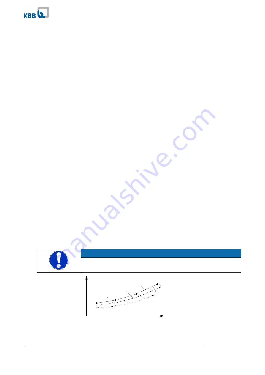
For dry running detection, the above-mentioned load curve is reduced via parameter
3-12-4-9
(see Fig.: Limit value curves for detecting dry running and hydraulic
blockage). If the current power is lower than the reduced load curve, the drive trips
with a delay (parameter
3-12-4-10
) and the Dry Running alert is output (see Fig.:
Limit value curves for detecting dry running and hydraulic blockage).
Hydraulic blockage
For hydraulic blockage detection, the above-mentioned load curve is reduced via
parameter
3-12-4-7
(see Fig.: Limit value curves for detecting dry running and
hydraulic blockage). If the current power is lower than the reduced load curve, the
drive outputs the Hydraulic Blockage warning after a delay (parameter
3-12-4-8
).
If dry running protection is deactivated via parameter
3-12-4-11
, the drive already
trips in the event of a hydraulic blockage and an appropriate alert is output.
NOTE
During the learning process, PumpDrive runs up to the maximum speed (parameter
3-6-1-3
) or up to the load limit, irrespective of the setpoint specification.
Frequency
3--12--4--7
Power
3--12--4--9
Saved load curve
Hydraulic blockage
Dry running
Fig. 42: Limit value curves for detecting dry running and hydraulic blockage
7 Commissioning/shutdown
PumpDrive
75 of 162


