FCU 500, FCU 505 · Edition 02.17
70
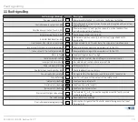
Fault signalling
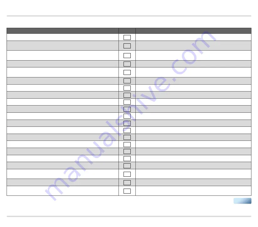
11 Fault signalling
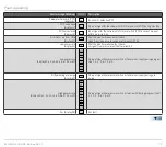
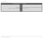
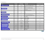
Fault message (blinking)
DISPLAY
Description
Too many remote resets
10
Remote reset activated > 5 × in 15 min.; faulty input actuation
Controller enable output (trm. 56)
20
Controller enable output incorrectly connected/supplied with power from
an external source
Simultaneous activation (trm. 51, 52)
21
“Maximum capacity” and “Ignition capacity” position feedback from
butterfly valve set simultaneously
Actuator wiring (trm. 52-55)
22
Faulty wiring of terminals 52 to 55
Actuator feedback (trm. 52)
23
Maximum or ignition capacity is not constantly signalled back to
terminal 52
Simultaneous Min./Max. bus command
24
“Open actuator” and “Close actuator” bus signals set simultaneously
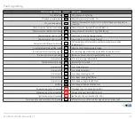
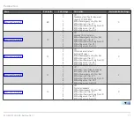
Inconsistent NFS (non-fail-safe) parameters
30
Abnormal data change in the parameters set for the FCU
Inconsistent FS (fail-safe) parameters
31
Abnormal data change in the parameters set for the FCU
Mains voltage
32
Supply voltage too low or too high
Faulty parameterization
33
Parameter set contains illegal settings or internal device error
Incompatible bus module
35
Bus module and control unit are incompatible
Power module defective
36
Relay contact error
Contactor function check (trm. 68)
37
Faulty feedback from contactors
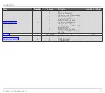
Fan not ready for operation
38
No signal at the “Fan feedback” input (terminal 44); fan defective
Fuse defective
39
Short-circuit on one of the outputs of the safety circuit
Inlet valve(s) leaking
40
Leak found on inlet valve(s)
Outlet valve(s) leaking
41
Leak found on outlet valve(s)
Burner valve(s) leaking
42
Leak found on burner valves
Pressure switch/gas valve wiring
44
Test volume (V
p1
or V
p2
) cannot be supplied or vented; faulty pressure
switch/gas valve wiring
Gas valve wiring
45
Reversed valve connection
Controller enable/emergency stop
50
Interruption of signal at the “Controller enable/Emergency stop” input
(terminal 46)
▼

