


DG..H, DG..N, DG..I · Edition 03.22
EN-8
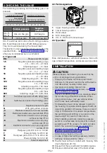
8.13 Red/green LeD for 24 V DC/AC or
110–230 V AC
24 V DC, I = 16 mA; 24 V AC, I = 8 mA, Order No.:
74921089.
110 to 230 V AC, Order No.: 74923275.
1
2
3
4
NC
1
COM
3
NO
2
N
NO
2
1 NC
3 COM
+
–
9 teCHnICAL DAtA
9.1 Ambient conditions
Max. medium and ambient temperatures:
DG..H, DG..N: -15 to +60°C (5 to +140°F),
DG..I: -20 to +80°C (-4 to +176°F).
Storage and transport temperatures: -20 to +40°C
(-4 to +104°F).
Icing, condensation and dew in and on the unit are
not permitted.
Enclosure: IP 54 or IP 65. Safety class: 1.
This unit is not suitable for cleaning with a high-pres-
sure cleaner and/or cleaning products.
9.1.1 Pressure switch with nBR diaphragm
Long-term use in the upper ambient temperature range
accelerates the ageing of the elastomer materials and
reduces the service life (please contact manufacturer).
Continuous operation with gases containing more than
0.1 %-by-vol. H
2
S or ozone concentrations exceeding
200 µg/m
3
accelerate the ageing of elastomer materials
and reduce the service life.
9.2 Mechanical data
Gas types: natural gas, town gas, LPG (gaseous),
flue gas, biogas (max. 0.1 %-by-vol. H
2
S) and air.
Max. inlet pressure p
max.
= withstand pressure, see
Max. test pressure for testing the entire system:
temporarily (< 15 minutes) 2 bar.
Diaphragm pressure switch, silicone-free.
Housing: glass fibre reinforced PBT plastic with low
gas release.
Lower housing section: AlSi 12.
Weight: 270 to 320 g depending on equipment.
9.2.1 Recommended tightening torque
Component
tightening
torque
[ncm]
Cover screws
65
M16 x 1.5 cable gland
50
½" NPT conduit
170 (15 lb")
Rp 1/8 pipe connection on
aluminium lower section
250
Rp 1/4 connection (1/4" NPT) on
aluminium lower section
1300
Rp 1/8 connection on upper
housing section
250
Clamping terminal screws
80
T15 test point screw
150
9.3 electrical data
Switching capacity:
U
I
(cos φ = 1)
I
(cos φ = 0.6)
DG
24–
250 V AC
0.05–5 A
0.05–1 A
DG..G
5–250 V
AC
0.01–5 A
0.01–1 A
DG..G 5–48 V DC
0.01–1 A
0.01–1 A
Conductor diameter: 0.5 to 1.8 mm (AWG 24 to
AWG 13).
Line entrance: M16 x 1.5, clamping range: 4 to
10 mm.
Type of connection: screw terminals.
10 DesIGneD LIFetIMe
This information on the designed lifetime is based on
using the product in accordance with these operat-
ing instructions. Once the designed lifetime has been
reached, safety-relevant products must be replaced.
Designed lifetime (based on date of manufacture)
in accordance with EN 13611, EN 1854 for DG..H,
DG..N, DG..I:
Medium
Designed lifetime
switching
cycles
time (years)
Gas
50,000
10
Air
250,000
10
You can find further explanations in the applicable
rules and regulations and on the afecor website (www.
afecor.org).
This procedure applies to heating systems. For ther-
moprocessing equipment, observe local regulations.


