


BCU 560, BCU 565 · Edition 02.16
74
Parameters
11 .5 Safety limits
Parameters 15, 16 and 19 can be used to adjust the safety limits
(low air pressure protection and safety time during operation)
to the system requirements.
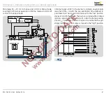
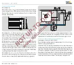
11 .5 .1 Low air pressure protection
Parameter 15
The minimum air pressure is ensured using the air
min.
air
pressure switch connected to terminal 47 while the fan for
the combustion air is switched on. Activation of the low air
pressure protection device and the shut-down properties
can be set using parameter 15. If the air pressure falls below
the value set on the air
min.
air pressure switch, the signal to
terminal 47 is interrupted and the BCU initiates a reaction
depending on parameter 15.
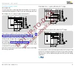
When the fan is switched off, the “no flow” state (default posi-
tion) of the air pressure switch (PDZ) is checked. To bypass
switching off the fan, the air supply to the pressure switch
can be interrupted by a 2/3-way valve. The 2/3-way valve is
actuated by terminal 58.
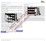
Parameter 15 = 0: Off; the low air pressure protection function
is deactivated.
Parameter 15 = 1: with safety shut-down. A safety shut-down
will be performed if there is no signal at the air
min.
input (ter-
minal 47).
Parameter 15 = 2: with fault lock-out. A safety shut-down with
fault lock-out will be performed if there is no signal at the
air
min.
input (terminal 47).
BCU 565
µC
P
49
15
13
14
50
45
p
e
/2
TC
PZL
PZH
PZ
ϑ
1
2
3
47
PDZ
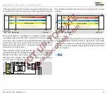
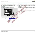
If air flow monitoring during pre-purge is active (P35 = 1
or 2), the “no flow” state of the air flow monitoring pressure
switch (PDZ) is also checked.
For further information on the low air pressure protection func-
tion (air
min.
, terminal 47, and air flow, terminal 48) during pre-
purge, see page 76 (Air flow monitoring during pre-purge).
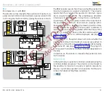
11 .5 .2 Air pressure cut-out delay
Parameter 16
This parameter defines whether the gas enable is sent to
terminal 47 with or without an air pressure switch signal. The
parameter can be adjusted if the low air pressure protection
is active (parameter 15 = 1 or 2).
Parameter 16 = 0: Off. Air pressure monitoring takes place
immediately. The gas is only released when the signal is re-
ceived from the air pressure switch. Parameter 48 (Air actuator
control) must be set to 1 for this function (air with 1
st
gas stage).
Parameter 16 = 1: On. The air pressure is monitored after a
delay of up to the maximum running time set in parameter
42 or until the position for maximum capacity is confirmed
by the actuator.


