


BCU 560, BCU 565 · Edition 02.16
22
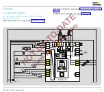
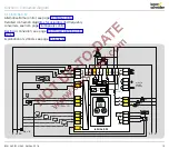
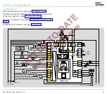
Function > Connection diagram
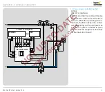
3 .1 .7 Flame control
Ionization control in single-electrode operation
1
2
3
46
45
65
66
67
68
49
50
51
17
18
37
38
13
14
15
N
L1
V1
V2
V3
max. 1 A;
24 V DC,
250 V AC
BCU 560..F1
3,15AT
µC
88
P70
P69
P70
P73
P72
P72
c
c
0 V
+24 V
41
42
24V
DC
HT
p
u
2
GZL
PZL
5 6
9
11 12
10
7
62 61
ϑ
A
P72
P71
230V
mA
(P40 = 2/3) => 51
52
53
54
55
56
P
Z
N
L1
0.6 × I
N
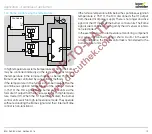
UVS control
1
2
3
46
45
65
66
67
68
49
50
51
17
18
37
38
13
14
15
N
L1
V1
V2
V3
max. 1 A;
24 V DC,
250 V AC
BCU 560..F1
3,15AT
µC
88
P70
P69
P70
P73
P72
P72
c
c
0 V
+24 V
41
42
24V
DC
HT
p
u
2
GZL
PZL
5 6
9
11 12
10
7
62 61
ϑ
A
P72
P71
230V
mA
(P40 = 2/3) => 51
52
53
54
55
56
P
UVS
1
2
3
Z
N
L1
0.6 × I
N
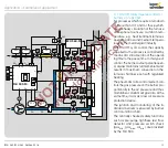
UVD control
1
2
3
46
45
65
66
67
68
49
50
51
17
18
37
38
13
14
15
N
L1
V1
V2
V3
max. 1 A;
24 V DC,
250 V AC
BCU 560..F1
3,15AT
µC
88
P70
P69
P70
P73
P72
P72
c
c
0 V
+24 V
41
42
24V
DC
HT
p
u
2
GZL
PZL
5 6
9
11 12
10
7
62 61
ϑ
A
P72
P71
230V
mA
(P40 = 2/3) => 51
52
53
54
55
56
P
0 V
24 V
+
–
0–20 mA
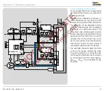
UVD1
1
2
4
3
5
6
Z
N
L1
0.6 × I
N
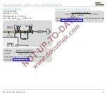
A voltage supply of 24 V DC is required to operate the UV
sensor for continuous operation UVD 1.
The 0 – 20 mA current output can be used to display the flame
signal. The cable to the control room must be screened. The
0 – 20 mA current output is not required for normal operation.


