


BCU 560, BCU 565 · Edition 02.16
110
Project planning information
13 .4 Actuators
If actuators are used, the start gas rate of the burners must be
limited for SIL 3 applications in compliance with the standard.
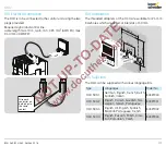
13 .4 .1 IC 20
The BCU..F1 checks the position to which the actuator IC 20
has moved using terminal 52 (feedback) by lifting the signal
to terminal 53, 54 or 55, see page 128 (Lifting).
To ensure this check is possible, BCU..F1 and actuator IC 20 or
equivalent three-point step actuators must be wired as shown
in the connection diagram.
1
2
3
46
45
65
66
67
68
49
50
51
18
37
38
13
14
15
N
L1
V1
V2
V3
max. 1 A;
24 V DC,
250 V AC
BCU 560..F0
3,15AT
µC
88
P70
P69
P70
P73
P72
P72
c
c
ϑ
0 V
+24 V
41
42
24V
DC
HT
LDS
p
u
2
GZL
PZL
P
5 6
9
11 12
10
7
62 61
I
Z
(BCU 560..F3 only)
(BCU 560..F3
only)
0.6 × I
N
13 .5 Parameter chip card
The parameter chip card must be installed in the unit for the
BCU to operate. The parameter chip card contains the valid
parameter settings for the BCU. If a BCU is replaced, the
parameter chip card can be removed from the old unit and
inserted into the new BCU. The BCU must be disconnected
from the electrical power supply for this purpose. The valid
parameters are then adopted by the new BCU. The old device
and the new BCU must have an identical type code.
13 .6 Overload protection
To protect the unit against overload by frequent cycling, only
a specific number of start-up attempts can be carried out
by the BCU. The maximum number of start-up attempts per
minute depends on the safety time t
SA
and the ignition time t
Z
.
t
SA
[s]
t
Z
[s]
Cycle lock
[s]
3
2
12
5
3
13
10
6
16
If too many start-up attempts are made,
53
flashes on the
display to indicate a fault.


