


SECTION 3
FRAMING
#LXL-22-L
R.1 4 . 2 0 . 2022
13
HUSSONG MFG. CO., INC.
KOZY HEAT FIREPLACES
Rough-in Vent Termination
3.3
Rough-in Vent Termination
This is a cold air transfer area. The gas stove rough-in must comply
with all clearances as outlined in this manual, and be constructed
in compliance with local building codes. Outside walls should be
insulated to prevent cold air from entering room.
Exterior vent termination location must be in compliance with section
5.2, MINIMUM TERMINATION CLEARANCES
on page 20. DO NOT
RECESS THE VENT CAP INTO WALL OR SIDING.
IMPORTANT - METAL FAB VENT SYSTEM:
When installing Metal Fab
vent pipe, an adapter must be used. This will increase the minimum
height for the center of the vent pipe by 3-1/4” (83mm) when framing
the wall pass through.
3.3.1
Clearances
•
A minimum of 1” (25mm) clearance on all sides of the vertical
vent pipe must be maintained.
•
A minimum of 1” (25mm) clearance from the top surface on the
horizontal pipe must be maintained.
•
A minimum of 1” (25mm) clearance on the sides and bottom
surfaces on the horizontal pipe must be maintained.
•
A minimum of 2-1/4” (57mm) clearance from the top of the
horizontal pipe to the ceiling is required. The horizontal pipe
after the wall pass-through must maintain a 1” (25mm) clearance
to combustibles on all surfaces of the pipe.
3.3.2
Vertical Terminations
Follow vent pipe manufacturer’s installation instructions for vertical
terminations.
•
Attic insulation shields may be insulated using unfaced
insulation products listed as non-combustible per ASTM E 136.
3.3.3
Horizontal Terminations
IMPORTANT: Horizontal vent sections require 1/4” (6mm) rise for every
12” (305mm) of travel.
•
Wall thimble products that comply with the required 1” (25mm)
clearances to combustibles must be installed for all horizontal
vent runs that pass through interior or exterior walls. These wall
thimble products may be insulated using unfaced insulation
products listed as noncombustible per ASTM E 136.
•
Elbows listed with approved vent systems for this appliance
vary in vertical length. Please consult the vent manufacturer’s
instructions to determine the elbow dimension used for
installation. Adjust the wall pass-through rough opening
dimensions to maintain clearance requirements.
3.3.3.1
Wall Pass Through Information and Framing
1.
Measure from floor level of the gas stove to the center of where
the vent pipe will penetrate the wall. The dimensions in
FIGURE
3.2
is used with a Simpson DuraVent elbow.
2.
Cut and frame an opening in the wall to allow the vent system to
run level through the wall pass-through.
3.
Follow the vent pipe manufacturer’s installation instructions for
vent installation.
•
Rigid pipe dimensions in
FIGURE 3.2
reflect Simpson
Duravent 4” x 6-5/8” coaxial pipe. Other manufacturers product
dimensions may vary.
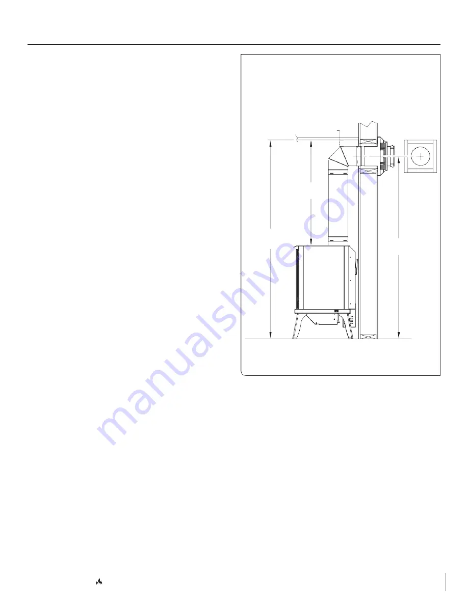
Natural Gas and Propane
Minimum Horizontal Venting
2
¼
”
Ceiling
(57mm)
36
¼
”
(920mm)
68
¼
”
(1734mm)
62 5⁄8”
(1591mm)
FIGURE 3.2
Rough-in Dimensions for Minimum Horizontal Venting