16 Sound Interface
Kontron User's Guide EPIC/CE
47
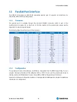
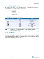
The individual pin-out of each jack connector is shown in the following table. (The configuration for
multi-channel applications is described in
Italics
)
Header
Jack
Pin
Signal Name
Function
2
AUXAL_C/
REAR_L
Line-input left.
Left Rear Speaker output for multi-channel applications
A
5
AUXAR_C/
REAR_R
Line-input right.
Right Front Speaker output for multi-channel applications
2
LEFT/
FRONT_L
Line-level stereo output left.
Left Front Speaker output for multi-channel applications
B
5
RIGHT/
FRONT_R
Line-level stereo output right.
Right Front Speaker output for multi-channel applications
2
MIC_C/
CENTER
Mono Microphone input.
Center Speaker output for multi-channel applications.
B
C
A
C
5
LFE
Low Frequency output for multi-channel applications.
16.1.2
Line-In/Rear Speakers Connector
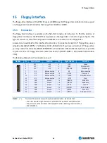
Line-In or Rear Speaker signals (depending on the configuration) are always available on Connector
X14. To find the location of the connector on the EPIC/CE board, please see the Appendix E: Connector
Layout chapter.
If using these signals as Line-In, a CDROM can be connected using a standard CDROM Audio cable.
The pin-out of this connector complies with the standard pin-out used in many commercially available
motherboards and it is shown in the following table.
Header
Pin
Signal Name
Function
4
AUXAL_C/
REAR_L
Auxiliary A input left. Normally intended for connection to an internal or
external CD-ROM analog output.
Left Rear Speaker output for multi channel applications
3
ASGND
Analog ground.
2
AUXAR_C/
REAR_R
Auxiliary A input right. Normally intended for connection to an internal or
external CD-ROM analog output.
Right Rear Speaker output for multi channel applications
1
4
1
ASGND
Analog ground.
16.2
Configuration
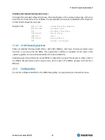
From the BIOS Setup Utility you can set the onboard legacy AC97 audio controller to Disabled or Enabled
(default). Refer to I/O Device Configuration submenu in the Appendix B: BIOS operation for more
details.
You can download available drivers for the sound controller from the Kontron Web site or use the drivers
provided by the manufacturer Realtek. Search for ALC650 drivers for the required operating system and
instructions on how to enable multi-channel support.
Содержание EPIC/CE
Страница 1: ...Kontron User s Guide EPIC CE Document Revision 1 14...
Страница 2: ...This page intentionally left blank...
Страница 88: ...25 Appendix C Block Diagram Kontron User s Guide EPIC CE 88 25 Appendix C Block Diagram...
Страница 90: ...26 Appendix D Mechanical Dimensions Kontron User s Guide EPIC CE 90 26 2 Connector Locations Pin 1...
Страница 93: ...27 Appendix E Connector Layout Kontron User s Guide EPIC CE 93 27 2 Bottom Side...


