32
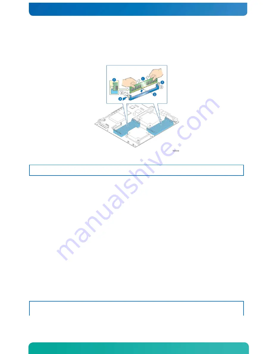
IMPORTANT: Visually check that each latch is fully closed and correctly engaged
with the notch on the DIMM edge. (“E”)
9.
Replace the air duct, riser card assembly, and back chassis cover if you have
completed all work inside of the server.
Figure 15. Memory DIMM Installation
Replacing or Removing Memory DIMMs
NOTE: To reduce the risk of electrostatic discharge (ESD) damage to the processor or
the DIMM, be sure to follow these procedures:
1.
Touch the metal chassis before touching the DIMM or server board.
2.
Keep part of your body in contact with the metal chassis to dissipate the static
charge while handling the DIMM.
3.
Avoid moving around unnecessarily.
4.
Use a ground strap attached to the front panel (with the bezel removed).
To remove a DIMM from the T5520UR server board, follow these steps:
1.
Remove the back chassis cover. For instructions see “Removing the Back Cover”.
2.
Remove the riser card assembly (so the processor air duct can be removed). For
instructions see “Removing the Riser Card Assembly”.
3.
Remove the processor air duct. For instructions, see “Removing the Processor Air
4.
Open the DIMM slot levers for the DIMM you want to remove.
5.
Using both hands, hold the DIMM by the edges and lift it up from the slot. Store
the DIMM in an anti-static package.
6.
If you are installing a replacement DIMM in this slot, return to Step 5 in
“Installing Memory DIMMs”.
Otherwise, replace the air duct, riser card assembly, and back chassis cover if
you have completed all work inside the server.
Adding or Replacing a Processor
CAUTION: The processor must be appropriate: You could damage the server board if you
install a processor that is inappropriate for your server. Refer to the


