18
381298/C
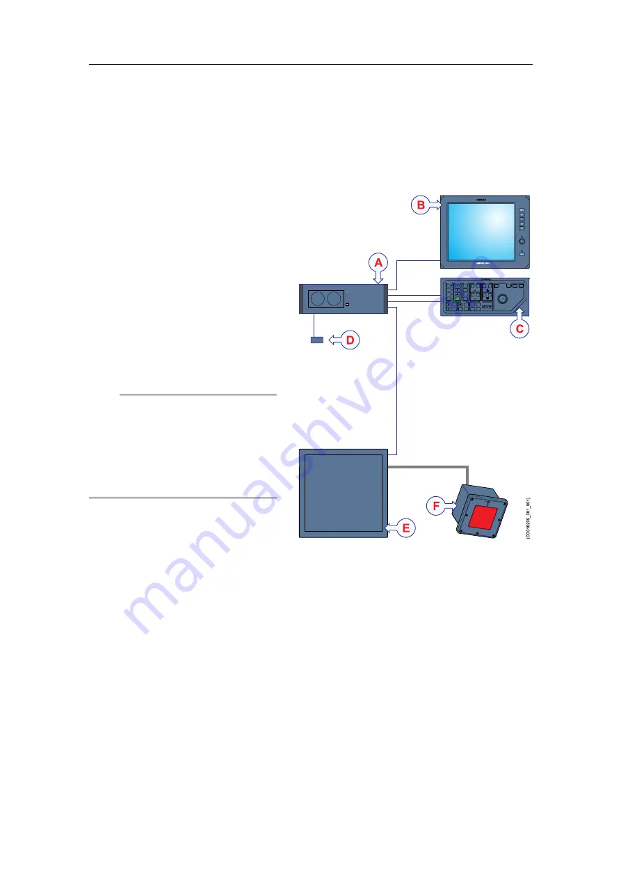
System diagram
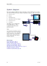
The system diagram identifies the main components of a basic SN90 system, as well as
the connections between the units. Interface capabilities and power cables are not shown.
SIMRAD
PWR
MENU
SIMRAD
SIMRAD SN90
(CD010205_001_001)
B
C
D
E
A
F
A
Processor Unit
B
Display
C
Operating Panel
D
Operating Panel Power Supply
E
Transceiver Unit
F
Transducer
The display is not a standard part
of the SN90 delivery. This is
a commercial item that can be
purchased locally.
Note
Each transducer installation must be
designed to fit the vessel’s hull shape
and characteristics. The installation
method and the cable penetration
must be approved by the relevant
maritime authority.
Related topics
System description, page 13
Display description, page 19
Processor Unit description, page 20
Transceiver Unit description, page 21
Operating Panel description, page 22
Operating Panel Power Supply description, page 22
Transducer description, page 23
Performance specifications, page 246
Simrad SN90
Содержание Simrad SN90
Страница 2: ......
Страница 117: ...381298 C 115 Related topics Installation summary page 65 Installing the transducer ...
Страница 226: ...224 381298 C 427 385 All measurements in mm The drawing is not in scale 385609 Rev B CD12_385609_001_002 Simrad SN90 ...
Страница 236: ...234 381298 C 372915 Clamping frame Simrad SN90 ...
Страница 295: ......
Страница 296: ... 2016Kongsberg Maritime ISBN 978 82 8066 179 1 ...
Страница 297: ......

