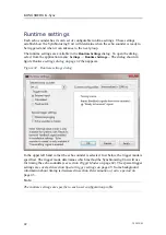
Kongsberg K-Sync Скачать руководство пользователя страница 47

OPERATIONAL PROCEDURES

External input mode

Figure 35

Runtime settings dialog - External input

Typically the trigger mode should be set to external input if the echo sounder provides a
ready to transmit signal. The Ready to Transmit and the Transmitting feedback signals
are configured as part of the installation settings. Only if the Ready to transmit signal is
configured will the External input selection be available.

342435/B

45

Содержание K-Sync

Страница 1: ...Operator Manual K Sync Synchronization Unit ...

Страница 2: ......

Страница 3: ...KONGSBERG K Sync Operator Manual Kongsberg Maritime 342435 B January 2021 Kongsberg Maritime AS ...

Страница 4: ...nd fairly stated but does not accept liability for any errors or omissions Warning The equipment to which this manual applies must only be used for the purpose for which it was designed Improper use or maintenance may cause damage to the equipment and or injury to personnel The user must be familiar with the contents of the appropriate manuals before attempting to operate or work on the equipment ...

Страница 5: ... settings 16 Depth datagram input 16 Estimation of travel time 17 Datagram output 17 Installation Settings 18 Managing Installed Systems 19 Configuring signal interface 21 Feedback signals from echo sounder 22 Trigger output to echo sounder 23 Specific signal settings 24 Configuration of GPTs and WBTs 25 Backing up and importing configuration files 26 Backing up K Sync configuration files 26 Impor...

Страница 6: ... 9 Allow modification 19 10 Password dialog 19 11 Installation Settings Manage Installed systems button 20 12 Manage Installed Echo Sounders dialog 21 13 Installation settings dialog 22 14 Installation settings Ready to transmit 22 15 Installation settings Transmitting 23 16 Installation settings Trigger output 23 17 Installation settings Advanced settings 25 18 Configure GPTs dialog box 26 19 Sys...

Страница 7: ...Runtime settings dialog External input 45 36 Runtime settings dialog Calculated 46 37 Runtime settings dialog Fixed period 47 38 Trigger pulse 48 39 Trigger display for EA 600 and OS 38 49 40 Trigger display for EA 600 EM 120 and SBP 120 50 41 User configuration profiles 51 42 Diagnostic display 52 43 Signals display 55 342435 B 5 ...

Страница 8: ...KONGSBERG K Sync 6 342435 B ...

Страница 9: ... The Synchronizing Unit provides simple yet flexible control of scheduling The trigger schedule can be tailored to the particular type of survey and desired data density collected by each system Any echo sounder that has a trigger input can be externally triggered by the Synchronizing Unit System overview This chapter provides an overview of the K Sync components and interfaces Main components The...

Страница 10: ... is running the application can be shut down and disconnected while the Synchronizing Unit continues to control the triggering of echo sounders The echo sounders are interfaced directly to the Synchronizing Unit as depicted in figure The complete synchronizing system on page 8 Network Interface A single network interface exists between the Workstation and the Synchronizing Unit The interface allow...

Страница 11: ...nchronizing Unit controls pinging and receives status from the echo sounders via the signal interface A trigger output is provided for each echo sounder as well as inputs for receiving feedback signals from echo sounders See figure The Synchronizing Unit on page 10 The Synchronizing unit provides one output and two inputs for each echo sounder Trigger signal output tells the echo sounder when to t...

Страница 12: ...ycle then the next group is triggered All groups are triggered in round robin fashion The duration of each group is not fixed and depends upon what the maximum active period is for the echo sounders in that group Echo sounders can be taken out of the schedule without changing the group schedule simply by disabling them If a group does not contain any available echo sounders then that group is skip...

Страница 13: ...n Windows 7 32 or 64 bit or Windows 10 32 or 64 bit Intel or AMD processor 2 GHz or higher 8GB RAM 1x 100 Mbps network interface card 256 GB HD Recommended screen resolution is 1280x1024 or larger Reference K Sync Installation Manual 342741 Operator Manual EM Series Datagram Formats 850 160692 342435 B 11 ...

Страница 14: ... the I O modules have been properly configured Workstation Setup Set up of Workstation includes configuration of the network card and installing the Workstation software Network Configuration The IP address of the Synchronizing Unit is by default 157 237 60 169 with a subnet mask of 255 255 240 0 It is highly recommended to use this configuration to make any possible future troubleshooting or supp...

Страница 15: ...nal levels have settled Proper installation can be verified by 1 Make sure echo sounders are turned off or at least pinging external trigger is turned off to avoid any spurious triggering during power up 2 Turn on the power to the Synchronizing Unit 3 Open the application Start menu All Programs Kongsberg Maritime K Sync Application on the Workstation 4 Once that application has started the status...

Страница 16: ... time a connection is made after power up System settings System settings dialog permits modification of settings related to external depth and sound speed used for travel time calculations The Synchronizing Unit is capable of receiving external depth datagrams sent over Ethernet The settings for defining UDP receive port and datagram types are available in the System Settings dialog Click on Sett...

Страница 17: ...SYSTEM CONFIGURATION Figure 4 System settings General 342435 B 15 ...

Страница 18: ...he IP address in the K Sync application the application should be restarted and one should verify that communication with synchronizing unit is functioning LED in system control turns green or yellow Depth datagram input The Synchronizing Unit can receive depth data from external sources Depth data is sent as datagrams directly to the Synchronizing Unit In order to receive depth externally a netwo...

Страница 19: ...Manual EM Series Datagram Formats 850 160692 Rev M for detailed description of depth datagrams Estimation of travel time The System sound speed setting is used for roundtrip time calculation when the operating mode for an echo sounder is set to calculated Since the setting only affects timing estimates it is not critical for the value to be continuously updated or be exact The value should be an a...

Страница 20: ...display in SIS The terms seen in the K Sync Application window are in parenthesis Color Description Dark green Echo sounder is ready active but not currently pinging Green SIS4 Echo sounder is pinging busy Blue SIS5 Echo sounder is pinging busy Yellow Echo sounder is unavailable standby Gray no color Echo sounder is not in use disabled Figure 7 K Sync status SIS4 Figure 8 K Sync status SIS5 Instal...

Страница 21: ...ord dialog Managing Installed Systems The Echo sounder systems to be controlled may already have been imported into the K Sync Application during the installation If not then new systems can be added via the Installation Settings dialog and selecting the Manage installed systems button 342435 B 19 ...

Страница 22: ...s dialog will allow new systems to be added or current ones to be deleted see figure on page All systems will be listed in alphabetical order in user interface such as the echo sounder status area and trigger display If echo sounder to be added is not available from the list it can be created by clicking the Create new button and entering make and model in the dialog that appears not shown 20 3424...

Страница 23: ...en a transmit occurs An echo sounder may or may not provide these signals Trigger pulse generated by Synchronizing Unit signals the echo sounder to transmit The echo sounder must explicitly be configured for external trigger mode to enable external trigger Usually an echo sounder will transmit at the same instant as the pulse is received However a few echo sounders will have an inherent delay or e...

Страница 24: ...can be found in Appendix A Feedback signals from echo sounder The feedback signals communicate whether an echo sounder is ready to be triggered and if transmit occurred Ready to transmit Figure 14 Installation settings Ready to transmit When the ready to transmit signal is active the Synchronizing Unit can trigger the echo sounder Once the ping cycle starts it is required that the signal go inacti...

Страница 25: ...t will assume that the echo sounder is no longer available The echo sounder is assumed to be not responding if it has not transmitted within 512 ms of trigger In this case it will be put into Standby and the system will not be triggered by the Synchronizing Unit until the operator disables and re enables the system in Echo Sounder Status see section Echo Sounder status on page 40 It is also possib...

Страница 26: ...voltage levels associated with this setting The level also depends on whether the input has been configured for TTL or RS 232 signal level To illustrate if the manufacturer specifies that the ready to transmit signal is TTL and active when voltage is 5V then from the table below the signal active should be configured as active high Likewise an RS 232 signal that is specified to be active when volt...

Страница 27: ... if TTL level and low if RS 232 Rising falling edge setting will then refer to actual rising falling edge with respect to voltage as opposed to logic level Configuration of GPTs and WBTs The configuration of GPTs General Purpose Transceivers and WBTs Wide Band Transceivers settings are applicable to echo sounders that are always triggered together but have individual feedback signals For example t...

Страница 28: ...files All settings that are used by the K Sync Application can be backed up as a ZIP file archive This will backup all system installation and runtime settings that are in use at any given point in time Back up configuration files 1 Select File Backup config files 2 In the Backup K Sync Application Config Files dialog 26 342435 B ...

Страница 29: ...der there are also backed up config files that are backed up during upgrade by application installer These files are saved to individual folders instead of ZIP files Importing K Sync configuration files Import restore configuration files 1 Go to File Import config files 2 In the Import K Sync Application Config Files dialog a Click the folder icon b Select the ZIP file archive to import By default...

Страница 30: ...n and if the application is able to connect to the synchronizing unit 4 Wait for the application to connect to the Synchronizing Unit The LED indicator in the top left corner System Control will remain red until successful connection with Synchronizing Unit The LED will then blink green A blinking green LED means the system is currently paused no triggering which is the default state after unit is...

Страница 31: ...to which groups Figure 21 Trigger Status 6 Once a system is triggered the Echo sounder status will show a green LED for the duration of the active period next to checkbox ACTIVE means the echo sounder is ready and will ping whenever triggered STANDBY means the echo sounder is not ready due to timeout see status log for specific reason DISABLED simply means the echo sounder is disabled in the K Syn...

Страница 32: ...ype of echo sounder If Calculated mode is selected then the multiplication factor should be 0 if single beam echo sounder This will cause the Synchronizing Unit to wait at least the duration of the two way roundtrip time travel time at the current depth A multibeam system will have a wider swath and consequently the roundtrip time will increase depending upon swath angle When Calculated is selecte...

Страница 33: ...reen gray indicates the state and the events of the echo sounder See the legend for description in figure Trigger display on page 38 Note that the plot will always show a red pulse whenever a transmit occurred when not externally triggered but free running Figure 25 Trigger display 10 The period of the trigger display can be set to 10 30 or 60 seconds The horizontal axis shows the current time 11 ...

Страница 34: ...KONGSBERG K Sync Read the chapter OPERATIONAL PROCEDURES on page 33 to learn more about configuring the K Sync in more detail 32 342435 B ...

Страница 35: ...ilizing user configuration profiles and interpreting the trigger display The runtime settings will also be explained in detail The K Sync Application serves to set up the Synchronizing Unit for proper operation but the Synchronizing Unit is self contained when it comes to performing the synchronization Figure K Sync application user interface on page 34 provides a screenshot of the user interface ...

Страница 36: ... the toggle button Caution Always power up Synchronizing Unit before other echo sounders are turned on to avoid accidental pinging Trigger outputs are undefined during power up first 20 seconds of Synchronizing Unit and signal levels could potentially be interpreted as trigger pulse by the echo sounders until signal levels have settled Once the K Sync Application has been started it will automatic...

Страница 37: ... click the toggle button and it will change to Running No echo sounder will be triggered until they have been enabled and assigned to trigger groups These settings will be explained later in this chapter In the case the K Sync Application loses the connection with the Synchronizing Unit the LED will again turn red If the Workstation becomes disconnected intentionally or if network connection fails...

Страница 38: ... Managing Installed Systems on page 19 Figure 28 System status current depth System status indicates that external depth is being received Trigger groups The trigger groups are the basis for scheduling of the echo sounders They specify in what order and which echo sounders will transmit together The specific timing of the individual echo sounders on the other hand is specified via the runtime para...

Страница 39: ... 29 Trigger group status Trigger group status shows which is the current group and the trigger group schedule indicates which group each echo sounder is assigned to The trigger group schedule shows one system per row and the trigger groups are grouped in columns A green LED indicates that the echo sounder has been assigned to that group To modify the schedule click the Configure button The dialog ...

Страница 40: ...y line Echo sounder has been disabled by operator or the echo sounder is in standby state i e timed out not ready Ready Green line Echo sounder is ready to be triggered Busy Red line Echo sounder is currently transmitting receiving and or processing samples i e not ready State plot Transmit Red pulse Echo sounder acknowledged that a transmit occurred width of pulse does not represent the duration ...

Страница 41: ...n be set depending upon the typical ping rate In deep water the display will be more readable if a longer duration is selected The display period can be set to 5 10 30 or 60 seconds The settings available are shown in figure Display settings on page 39 Figure 32 Display settings The trigger display settings allow the width of the display to be modified and the group marker to be enabled or disable...

Страница 42: ...t will be triggered according to the schedule see figure Trigger groups echo sounders on page 37 if disabled it will not be triggered at all This setting is located on the left hand side of the echo sounder status area of the user interface see figure Echo sounder status display on page 40 There are several indicators shown along with each echo sounder in this display The green Busy LED is on when...

Страница 43: ...ed for this echo sounder see section Runtime settings on page 42 for more information The active period displays the duration in seconds from time of trigger until echo sounder has completed its ping cycle It shows the latest recorded value The inverse of this value is the maximum theoretical ping rate if this echo sounder was triggered by itself If the echo sounder is set to calculated or fixed p...

Страница 44: ...own in figure Runtime settings dialog on page 42 then appears Figure 34 Runtime settings dialog In the upper left hand corner the echo sounder is selected Just below the trigger mode is specified The trigger mode determines which method the Synchronizing Unit will use for timing the echo sounders see section Trigger Modes on page 44 The special trigger settings are covered in section Special trigg...

Страница 45: ...eristics of the echo sounder For most echo sounders the duration depends upon depth For example the duration may be the roundtrip time two way travel time of the ping plus additional time needed for processing or to permit below sea floor data sampling The relationship between active period and depth can be modeled by the following formula In this formula active period is estimated as a function o...

Страница 46: ...red Calculated The active period is estimated based on current depth see formula is preceding section Fixed period The active period is set to a fixed period When the echo sounder provides a ready to transmit signal and the trigger mode is set to External input the Synchronizing Unit will depend solely on the feedback signal of the echo sounder to notify when its ping cycle is complete If this sig...

Страница 47: ... mode should be set to external input if the echo sounder provides a ready to transmit signal The Ready to Transmit and the Transmitting feedback signals are configured as part of the installation settings Only if the Ready to transmit signal is configured will the External input selection be available 342435 B 45 ...

Страница 48: ...m adds a fixed delay regardless of depth The following two parameters are entered in the Roundtrip time calculation parameters area of the Runtime Settings dialog Multiplication factor This value increases the period proportionally to depth due to wide swath or pointing angle off nadir The value can be set from 0 to 600 percent Knowing the maximum pointing angle Table Basis for determining multipl...

Страница 49: ...me of a normal incidence sounding at current depth Runtime parameters are unique for each profile so it is possible to set up different parameters depending on the specific requirements of the survey Fixed period mode Figure 37 Runtime settings dialog Fixed period When using fixed period trigger mode only the period can be specified Ready to transmit signal will be ignored for timing purposes if p...

Страница 50: ...edule or disable them 2 Set the echo sounder to use calculated trigger mode if single beam or multibeam echo sounder use fixed period otherwise 3 If set to calculated determine multiplication factor based on maximum pointing angle use table Basis for determining multiplication factor based on maximum angle of incidence on page 47 This establishes the theoretical minimum active period based on maxi...

Страница 51: ...e unpredictable active periods from one ping to the next The maximize pinging feature assumes that the next ping cycle will take the same amount of time as the previous one Figure 39 Trigger display for EA 600 and OS 38 Trigger display showing EA 600 top configured to maximize pinging The EA 600 is able to ping multiple times while the OS 38 bottom is performing a single ping Echo sounder is maste...

Страница 52: ...ostic display on page 52 the EM 120 is configured as master As with all the runtime settings they are independently configured for each user configuration profile In the figure Trigger display for EA 600 EM 120 and SBP 120 on page 50 the EM 120 is set up as master and is triggered first blue pulse The other two echo sounders are triggered once the EM 120 has transmitted red pulse Figure 40 Trigger...

Страница 53: ...s The following actions are supported when managing the configuration profiles Table 8 Select profile from list Recalls settings from an existing profile Set as default Set the selected profile as the default Save Save current settings to an existing profile overwrite New Create a new profile using current settings with a specified name Delete Delete an existing profile The K Sync Application come...

Страница 54: ...abel next to each LED describes which module and terminal number it is associated with The module and terminal number refer to the physical connections inside the Synchronizing Unit Note The LEDs refer to the actual voltage level on the input referred to as 5 V If signal conditioning has been applied the states may become inverted For instance if signal is set up for RS 232 the LED is on when volt...

Страница 55: ... antivirus application blocking communication 8 Windows firewall passes through traffic to synchronizing unit 9 Try disabling all network interfaces and only configure the IP subnet for the synchronizing unit Status log Echo sounder is no longer available ready to transmit timed out Standing by Make sure the echo sounder is set up for external trigger check settings for the echo sounder itself Pin...

Страница 56: ...ting signal and the signal is enabled in the installation settings Echo sounder state toggles between standby and active Check that the installation parameters for ready to transmit are correct correct input terminal Correct signal active level Echo sounder goes to standby mode inadvertently and stops pinging when surveying in deep water Check that the ready to transmit timeout parameter in the in...

Страница 57: ...transitions that are relevant to timing are indicated by an arrow This illustration assumes that both ready to transmit and the transmitting feedback signals are provided by the echo sounder If ready to transmit is not available then the period is estimated based on runtime settings provided If transmitting signal is not available it is not possible to know when transmit occurred In the latter cas...

Страница 58: ...fied so the state plot in the trigger display shows a red pulse 4 Transmit typically occurs immediately after the trigger pulse has been received by the Synchronizing Unit The duration from trigger pulse until actual transmit is the ping latency 5 Trigger pulse width This property can be set in the installation settings 6 Echo sounder has completed receiving samples and processing for this ping Th...

Страница 59: ...conds Max trigger groups 16 Signal latency feedback signal to trigger output 40 μs Timing resolution of synchronization calculated or fixed trigger mode 4 ms Available signal inputs 12 24 36 or 48 Max systems trigger outputs 4 8 12 or 16 Supported signal levels inputs and outputs TTL and RS 232 Supported depth datagram input Kongsberg EM D X and E Kongsberg EA 500 NMEA DPT and DBS Depending upon d...

Страница 60: ... input trigger mode One of three trigger modes available for scheduling The estimated active period is equal the time between trigger and when ready to transmit becomes active See also Calculated trigger mode Fixed trigger mode Fixed trigger mode One of three trigger modes available for scheduling The estimated active period is set equal to a fixed period See also Calculated trigger mode External ...

Страница 61: ...eady or failed to transmit upon being triggered See also Active state Disabled state Transmitting signal Feedback signal provided by an echo sounder in order to determine if and when a transmit occurred See also Ready to transmit signal WBT Wide Band Transceiver Refers to transceiver units for a product line of newest KONGSBERG single beam echo sounders EK80 EA640 etc WBTs are set up using Configu...

Страница 62: ... 2021 Kongsberg Maritime ...

Отзывы: