64
922-20207011/1.0
Installing the VDSL cables
VDSL telemetry allows you to use longer cables than Ethernet telemetry.
Context
If you are using VDSL telemetry, you must install a VDSL modem to interface between
the Sonar Head and Sonar Processor or ROV Topside Unit
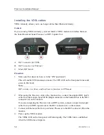
A
RJ11 connector for VDSL
B
RJ45 connector for Ethernet
C
Mode DIP Switch
Procedure
1
Make sure that dip switch one is in the “ON” position (C).
This will enable CPE transmission mode. The CPE LED on the front panel turns solid
green in this mode.
Note
DIP switches two, three, and four have no function in CPE mode.
2
When using the Flexview cable with a breakout box, connect the supplied RJ11 patch
cable from the four-pin Sync/VDSL Bulgin connector on the breakout box to the RJ11
connector (A) on the modem.
If you are integrating the Flexview into an ROV system, connect a single twisted-pair
cable from your ROV topside unit to the RJ11 connector (A) on the modem.
3
Connect an Ethernet cable from your Sonar Processor to the RJ45 connector (B) on the
modem.
4
Power up the VDSL modem.
The VDSL LED on the front panel will blink rapidly. The VDSL link is established
when the LED turns solid green.
Flexview Installation Manual
Содержание Flexview
Страница 1: ...Installation Manual Flexview Multibeam Sonar ...
Страница 2: ......
Страница 8: ...6 922 20207011 1 0 Flexview ...
Страница 95: ...922 20207011 1 0 93 Flexview Sonar Head 500 kHz outline dimensions Drawing file ...
Страница 96: ...94 922 20207011 1 0 Flexview Installation Manual ...
Страница 97: ...922 20207011 1 0 95 Drawing file ...
Страница 98: ...96 922 20207011 1 0 Flexview Sonar Head 950 1400 kHz outline dimensions Flexview Installation Manual ...
Страница 99: ...922 20207011 1 0 97 Drawing file ...
Страница 100: ...98 922 20207011 1 0 Flexview Installation Manual ...
Страница 126: ... 2019 Kongsberg Mesotech ...

