397152/E
17
Connecting the transponder to external
power and responder signals
The transponder can also be used as a responder unit.
Prerequisites
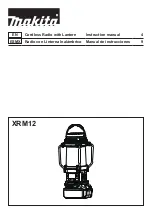
The transponder must be charged before use. This is the pin configuration for a male
connector, as seen towards the connector (face view).
1
2
3
4
Responder t
5
Responder trigger -
6
On/Off
7
External power (24 VDC)
8
Ground
Procedure
1
Use the cable with part number 402462 from Kongsberg.
2
Connect wire 6 and 8 in the pigtail (the ON/OFF function).
When 6-8 are linked, the transponder is ON.
With no connection between 6-8, the transponder is OFF.
3
Make sure that the external power supply 24 VDC is between 20 and 28 VDC.
4
Check the responder trigger signal.
5
Switch ON the unit by inserting the external power/responder cable.
Further requirements
It is recommended to test the transponder with the Test and Configuration unit (TTC) to
make sure it is working properly before operation.
Содержание cNODE MiniS
Страница 1: ...397152 E September 2022 Kongsberg Maritime AS cNODE MiniS Transponder Instruction Manual ...
Страница 6: ...6 397152 E cNODE MiniS ...
Страница 37: ...397152 E 37 cNODE MiniS 3x 180 dimensions Drawing file ...
Страница 38: ...38 397152 E cNODE MiniS 3x 40V dimensions cNODE MiniS Instruction Manual ...
Страница 39: ...397152 E 39 cNODE MiniS 34 S dimensions Drawing file ...
Страница 41: ...397152 E 41 Transducer guard dimensions Drawing file ...
Страница 42: ...42 397152 E Floating collar dimensions cNODE MiniS Instruction Manual ...
Страница 43: ...397152 E 43 TDR180 dimensions Drawing file ...
Страница 44: ...44 397152 E TDR40V dimensions cNODE MiniS Instruction Manual ...
Страница 45: ...397152 E 45 TDR30H dimensions Drawing file ...
Страница 62: ... 2022 Kongsberg Maritime ...