SIA KOMFOVENT reserves the right to make changes without prior notice
Fire damper UVS120 H (Two-Bladed design) ∙
I
nstallation manual ∙ 21-01
10
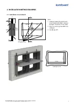
7. Fill in the gap between the casing and supporting construction with prescribed type of the filler and let the filler dry
out completely.
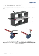
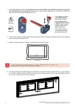
8. Visually check that fire damper is securely installed into the supporting construction, check if the fuse element and
levers system are undamaged and check if the blade is closing and opening properly by pressing “Push’ button
several times. The blade must be fully closed and no seizing should be observed.
9. When fire damper is fully installed and verified, make sure it is left in its normal working position with blade OPEN.
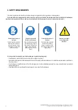
10. Please consider that all EU working safety and Fire safety standards must be observed during the installation
process.
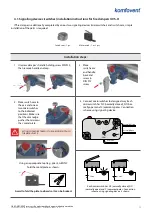
11. End position microswitches is an additional option that can be used to identify the blades position from a distance.
For each position of the blade (OPEN / CLOSE) one end switch is needed. Meaning in total it will be two end
position switches for one fire damper. It is easy to mount end positions switches on fire dampers with plastic
actuation mechanism – only one additional plastic part must be installed. This plastic part comes as a set with the
switches.


