background image

29

UAB KOMFOVENT we reserve the right to make changes without prior notice

RHP PRO_22-01

1

4

4

Ø D

6

6

3

4

Min. 10 x D

2

5

5

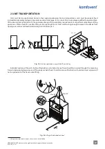
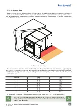
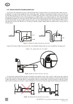
Fig. 28. 

Accessories for outdoor installed units

1 – air handling unit, 2 – air intake hood, 3 – roof, 4 – boxes or covers for air damper actuators, 

5 – air shut-off dampers, 6 – additional air dampers for protection of a stopped unit

• 

Air intake and outlet hoods must be installed as far apart as possible (for example by installing 

additional duct segments between AHU and hood), to prevent the exhaust air from returning to 

the air intakes.

a

b

c

d

a+80

b+80

c

d+80

b+80

d+80

a+80

c

c

a

b

d

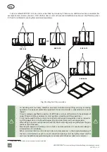
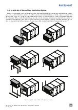
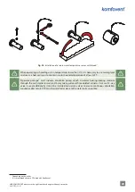
Fig. 29. 

Installation of a separately ordered protective roof

1

1  

Part count and measurements may differ depending on the unit type or project requirements.

Содержание RHP Pro

Страница 1: ...INSTALLATION MANUAL EN RHP Pro ...

Страница 2: ......

Страница 3: ...tallation Base 19 3 2 Inspection Area 21 3 3 Connection of Sections 22 3 4 Installation of External Heating Cooling Devices 23 3 5 Connection of a Condensate Drain 26 3 6 Connection to Air Ducts 27 3 7 Outdoor Units 28 4 ELECTRICAL INSTALLATION 30 4 1 Requirements for Electrical Connection 30 4 2 Connection of Electrical Components 32 4 3 Control Panel Installation 36 4 4 Connection of Cables and ...

Страница 4: ...ittothemainsincaseofanyvisibledamageincurredduringtransportation Do not leave foreign objects and tools inside the unit It is forbidden to operate air handling units in areas with potentially explosive atmospheres Use appropriate safety equipment gloves goggles when performing installation or repair works Heat pump system is filled with refrigerant F gas therefore only qualified refrigeration syst...

Страница 5: ...will lead to inefficient opera tion of a heat exchanger RHP air handling units with a rotary heat exchanger and an integrated heat pump Rotating wheel rotor of a rotary heat exchanger collects heat or cold from the indoor air and transfers it to the fresh supply air Recovered heat cold capacity is changed by adjusting the rotor speed When heat recovery is not required the wheel stops If a heat exc...

Страница 6: ...ached to the section door The following are the main sections of the air handling unit For equipment and number of sections in each unit see the technical data print out of the specific unit 1 3 1 Filter Fan Section Air handling units have two filter fan sections Filter contamination is measured and fan is controlled by an electronic circuit board fitted in the same section 1 2 3 1 2 3 5 4 Fig 1 F...

Страница 7: ...omation box to which many of the main electrical components are connected see Chapter Connection of Electrical Components 1 5 2 4 3 6 8 7 5 9 10 8 3 2 37 38 39 40 41 42 43 44 45 46 47 48 13 14 15 16 17 18 19 20 21 22 23 24 25 26 27 28 29 30 31 32 33 34 35 36 1 2 3 4 5 6 7 8 9 10 11 12 Fig 2 Heat pump section 1 main power switch 2 C5 controller main board 3 heat pump control electronics 4 rotary re...

Страница 8: ...ectric motor with a gearbox Brush seals are installed at the perimeter of a rotating drum and between airflows to prevent different airflows from mixing 1 2 3 7 7 4 3 6 5 4 Fig 3 Rotary heat exchanger assembly 1 C5 controller main board 2 automatic circuit breakers 3 rotary wheel 4 motor with gearbox 5 pulley for rotor belt 6 rotor belt 7 sealing brushes ...

Страница 9: ... 1 3 9 16 15 10 HPT HP EXV 13 14 12 11 8 8 8 8 2 11 7 1 14 6 9 17 18 5 4 16 3 12 15 13 10 17 18 19 Fig 4 Hydraulic circuit diagram and components of the heat pump 1 Compressor 2 4 way valve SVR 3 Defrost valve SVD 4 Low pressure transmiter LPT 5 Low pressure pressostat LP 6 Suction gas temperature sensor ST 7 Discharge gas temperature sensor DT 8 Check valve 9 Refrigerant coil positioned in the ex...

Страница 10: ...PLINKĄ Fig 5 Example of a heat pump s information label Heat pump is activated automatically when a rotary heat exchanger is unable to reach desired temperature and is switched off as soon as desired temperature is reached Frequent starting and stopping of a heat pump may damage com pressor therefore when heating cooling demand is low the heat pump will continue running for some time after the set...

Страница 11: ...re limit This results in reduced operating life and increased probability of failure During winter operation when the heat pump is in heating mode condensate on the evaporator starts freezing and forms frost Large ice deposits block airflow in the evaporator and may damage the heat pump Therefore the evaporator is automatically defrosted during winter use When the outdoor temperature drops below z...

Страница 12: ...01 EN 1 3 3 Recirculation Section Recirculation section is intended for mixing extract and supply air for heating or cooling thereof by reducing energy consumption of heaters coolers 1 2 3 1 2 Fig 7 Recirculation section 1 air mixing damper 2 damper actuator 3 recirculation section label ...

Страница 13: ...d which prevents condensate from entering other parts of the unit or air ducts 1 2 3 4 2 3 1 Fig 8 Cooler section 1 drop eliminator 2 coil for water refrigerant 3 condensate tray 4 cooler section label Depending on the order electric or water heaters may be selected An electric heater section is fitted with heater control electronics and the main circuit breaker see Chapter Requirements for Electr...

Страница 14: ...te the unit and to protect against air flows and draughts when the unit is stopped Damper blades are closed opened with an electric actuator 24 V AC the power and torque of which is selected according to a damper size Rectangular air ducts may be connected directly to dampers see Chapter Connection of Air Ducts For outdoor installation air dampers with electric actuators must be protected against ...

Страница 15: ...and location of a silencer section suppressor sections may be separate for each air flow e g for supply air only or double intended for both air flows Silencer section is equipped with noise absorbing partitions which can be removed and cleaned during inspection works Silencer section may also be equipped with an optional compact filter 1 2 1 Fig 11 Noise suppressor section 1 removable noise absor...

Страница 16: ...ir duct SUP position L1 Air duct for supply air connected on the left bottom side of the unit ODA EHA SUP ETA L2 Air duct for supply air connected on the left upper side of the unit ODA EHA SUP ETA R1 Air duct for supply air connected on the right bottom side of the unit ODA EHA SUP ETA R2 Air duct for supply air connected on the right upper side of the unit ODA EHA SUP ETA outdoor intake air air ...

Страница 17: ...g operations When a forklift is used for lifting or transporting the unit forks must be long enough to prevent the device from tipping over or to avoid mechanical damage to its bottom part Max 2 m L L Max 4 m Fig 12 Unit transportation using a forklift or a trolley Individual sections of the unit shall be lifted with an installation frame Pipes should be inserted through the mounting frame into de...

Страница 18: ... forklift truck or crane and familiar with the principles of cargo lifting and safety requirements must perform unloading or lifting operations It must be ensured that the casing is not crushed or otherwise damaged by straps or ropes dur ing lifting operations Use of special supporting structures traverses is recommended When lifting the unit or section thereof note that their center of gravity ma...

Страница 19: ... installed in a room with high humidity level condensate may form on the walls of the unit at low outdoor temperatures An air handling unit must be mounted on a relatively large and sturdy base based on the weight of the unit and in ac cordance with building regulations Base must be made of reinforced concrete or metal structures If the unit is not equipped with adjustable height feet it must be i...

Страница 20: ...out prior notice RHP PRO_22 01 EN As large unit sections may be difficult to connect properly on site and the unit door may warp it is necessary to adjust the hinges Loosen the lock screw to raise lower the door by a few millimetres Fig 16 Adjusting the hinges ...

Страница 21: ...h must be free of any stand alone or immovable devices equipment parti tions structure or furniture This area is sufficient for performing service and filter replacement works For repair and replace ment of components e g removal of rotary heat exchangers access area equal to the width of the device B shall be ensured in front of the device Unit size A mm B mm 10 670 1000 20 800 1150 30 800 1300 4...

Страница 22: ...crew M10 5 adhesive gasket 6 gasket on a shelf between different air flows 7 external tightening elements 8 internal tightening brackets Depending on the unit size and purpose of sections thereof separate sections may be interconnected with external tightening elements or internal tightening brackets using supplied screws Sealing gaskets must be attached to joints be fore joining the sections supp...

Страница 23: ...e supply air stream For air handling units with R1 or L1 inspection sides heater cooler sections are mounted on an installation frame and connected at the bottom part of the unit For R2 and L2 inspection side units heater cooler sections are mounted at the top part of the unit and must be additionally fastened or suspended fastening suspending accessories not included Heat exchanger sec tions are ...

Страница 24: ...al heater sections require a separate power supply All connections to the heating or cooling system piping and mains must be performed by a qualified specialist Fig 20 Connection of sleeves When connecting sleeves of water heaters coolers use two pipe wrenches to secure sleeves otherwise they will be dam aged If water is used in the heater for frost protection return water temperature sensor B5 mu...

Страница 25: ...aintain a return water temperature of at least 25 C Pipework package2 must include circulation pump which circulates heating cooling medium through the coil smaller circuit and 3 way mixing valve with modulated actuator In cases if 2 way valve is used additionally it must be installed non return valves to ensure continuous circulation around smaller circuit PPU must be installed as close to the wa...

Страница 26: ...er cannot drain out of the conden sate collection tray by itself Therefore it is necessary to connect a proper height siphon or a siphon with a one way valve to the drain pipe p 0 p 0 H mm H mm H 2 mm Ø40 mm Ø40 mm Fig 23 Installation of a siphon without a one way valve Height H of a siphon without a one way valve is selected according to static pressure p inside the air handling unit H mm 25 p mm...

Страница 27: ...ct system elements must have separate brackets and must be mounted in a way that their weight is not shifted to the unit casing Air ducts shall be connected to flexible unit connections flanges or air dampers Depending on the AHU size L 20 or L 30 flanges shall be used Special adhesive gasket must be attached to flanges for airtightness of air ducts We recommend installing a solid gasket i e do no...

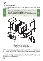
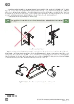
Страница 28: ...fects by installing a protective roof and exhaust air hoods Units shall be mounted on an installation frame which is attached to an installation base Ventilation devices when possible should be installed near the walls for protection against wind loads For outdoor installation units with drainage pipes must be additionally protected against freezing for example with electric heating cables for dra...

Страница 29: ...f dampers 6 additional air dampers for protection of a stopped unit Air intake and outlet hoods must be installed as far apart as possible for example by installing additional duct segments between AHU and hood to prevent the exhaust air from returning to the air intakes a b c d a 80 b 80 c d 80 b 80 d 80 a 80 c c a b d Fig 29 Installation of a separately ordered protective roof1 1 Part count and ...

Страница 30: ...ng diagram for your unit according to the unit type 4 1 Requirements for Electrical Connection Connect the unit only to a proper power outlet with protective earthing Earthing must be in stalled according to the EN61557 BS 7671 requirements It is recommended to connect AHU to the mains via automatic circuit breaker with 300 mA cur rent leakage protection type B or B Control cables should be instal...

Страница 31: ... section 1 lead in cable grommet 2 main circuit breaker handle 3 main circuit breaker 4 automatic switch 5 electronic heater control board Large RHP PRO units size 60 and larger also has a separate power circuit breaker for the heat pump section Lead in cable diameter depends on a maximum current specified in the technical data print out of the specific unit Current A Cable type 15 5 1 5 mm2 Cu 21...

Страница 32: ... automation box Automation box is fitted at the top part of the heat exchanger section Fig 32 Location of the automation box 37 38 39 40 41 42 43 44 45 46 47 48 13 14 15 16 17 18 19 20 21 22 23 24 25 26 27 28 29 30 31 32 33 34 35 36 1 2 3 4 5 6 7 8 9 10 11 12 25 26 27 28 29 30 1 2 2 3 4 1 Fig 33 Main board of the C5 control panel 1 control panel connection 2 Intranet or Internet connection 3 inner...

Страница 33: ... from a building management system via Modbus RTU protocol External management 4 8 terminals for controlling specific functions of the unit via external contacts which are connected to a common terminal 8 These include thermostats switches motion sensors and other devices with normally open or closed contacts Activated functions will operate as long as those contacts are connected Terminal 4 is us...

Страница 34: ... 12 terminal for a supply air temperature sensor NTC 10kΩ for controlling air temperature Fig 37 Supply air temperature sensor For the most accurate temperature measurement sensor in a duct must be installed after all heating cooling devices at least two duct diameters away from the nearest coil D 2D Fig 38 Installation of a supply air temperature sensor 1 Depending on the order 2 Depending on the...

Страница 35: ... these terminals are used for DCV airflow control when a separate 0 10 V signal can be used to adjust the ventilation intensity see User Manual FG1 37 39 terminals used to connect air damper actuators Also terminals are dedicated for smoke by pass damper actuator when optional smoke extraction function is ordered and fans are forced during fire alarm These terminals may also be used for connecting...

Страница 36: ...ller is supplied with a 10 m cable If this cable is too short you can replace it with a 4 0 22 mm cable up to 150 m long 1 2 3 4 24V LIN A LIN B GND RJ9 A B 150 m 4 x 0 22 mm2 Fig 39 Control panel wiring diagram Control panel cable shall be installed further away from other power supply cables or high voltage electrical equipment electrical enclosure electrical water heating boiler air conditionin...

Страница 37: ...etween the sections Refer to the wiring diagram of the specific unit to see what connections should be used X 1 X 2 X 1 2 X 1 X 2 X 1 2 2 3 1 Fig 41 Cable connections between sections 1 power supply cable 2 communication cables between circuit boards 3 labels with connection numbers Some components e g damper actuators humidifier etc do not have separate connectors and must be connected to a termi...

Страница 38: ...it open the network settings and manually assign an IP address the last number of which would be different from the unit s IP address for example if the unit s IP address is 192 168 0 50 assign the address 192 168 0 70 to the computer Enter the subnet mask 255 255 0 0 Internet Protocol Version 4 TCP IPv4 Properties General Obtain an IP address automatically Use the following IP address Use the fol...

Страница 39: ...AS Prisijungimasvidiniamekompiuteriniametinkle Prisijungimasinternetu Komfovent programėlė Komfovent programėlė Connection to the local computer network Connection via the Internet Komfovent C5 app Komfovent C5 app INTERNET Fig 45 Examples for the AHU connection to the Internet or the local network ...

Страница 40: ... It continuously measures pressure difference up stream and downstream the filter to evaluate level of contamination Filter replacement intervals depend on the environ ment pollution conditions as well as time of year for example during spring and summer filters may be contaminated with pollen pubescence or insects therefore change intervals are shorter Replace filters if they are visibly dirty ev...

Страница 41: ...is may distort air volume meas urements required for stable operation of the fans Do not use the unit with a temporary electrical power supply as unstable power can damage the electronic components See the KOMFOVENT website for user manuals The unit is controlled via a remote controller or a computer The unit is supplied with the following operation modes that may be used immediately after install...

Страница 42: ...it or change a ventilation mode Change operation mode During the first minute of starting the unit the unit automation checks the settings automation components and opens air dampers Later a signal is sent to fans and a heat exchanger and the unit starts operating at a selected ventilation mode To change the ventilation mode settings select a desired mode and set a desired air volume or temperatur...

Страница 43: ...e the use of all Proxy servers that may block the connec tion in the settings In the web browser address bar enter the IP address of the unit C5 Komfovent 192 168 0 50 Login to the C5 control panel interface in a window that opens enter the user name user password user1 and press CONNECT If you login attempt is successful Overview window is opened Modes Overview Alarms Status Functions Settings Sc...

Страница 44: ...otice RHP PRO_22 01 EN To start the unit and change the ventilation mode settings 1 Press button Modes 2 Select a desired ventilation mode from the list 3 Enter desired air flow and temperature in the selected mode settings 4 Press Save button at the bottom of the screen ...

Страница 45: ...ferent filtering class we recommend performing initial calibration of clean filters before commissioning of the unit During calibration the unit will operate at a maximum speed for a few minutes measure the pressure difference upstream and downstream the filter and automatically set the filter filtration class Calibration of clean filters with the control panel Start calibration Calibration of fil...

Страница 46: ... noise or vibrations Changing the ventilation modes changes the fan speed The unit is airtight without gaps or air leakage Heating cooling devices are working Connected external devices are working The condensate easily flows from the unit and the drainage piping is watertight Check for leaks in the heat pump piping system Check if there is no moisture in the refrigerant system The heat pump compr...

Страница 47: ......

Страница 48: ...433 info komfovent lv www komfovent lv Vidzemes filiāle Alejas iela 12A LV 4219 Valmiermuiža Valmieras pagasts Burtnieku novads Tel 371 29 358 145 kristaps zaicevs komfovent com www komfovent lv PARTNERS AT J PICHLER Gesellschaft m b H www pichlerluft at BE Ventilair group www ventilairgroup com ACB Airconditioning www acbairco be CZ REKUVENT s r o www rekuvent cz CH WESCO AG www wesco ch SUDCLIMA...

Отзывы: