26
UAB KOMFOVENT we reserve the right to make changes without prior notice
RHP PRO_22-01
EN
3.5. Connection of a Condensate Drain
During operation of the heat pump, air humidity condensates and accumulates in specially designed condensate trays.
Condensate is removed from condensate trays via drainage pipes, therefore a condensate drainage system must be con-
nected. Drainage piping must be at least 40 mm in diameter, mounted with a slope, without narrowing sections or loops
preventing water from draining. If such drainage piping is installed outdoors or in unheated premises, it must be adequately
insulated or equipped with a heating cable to prevent water from freezing during winter. Drainage piping is connected to
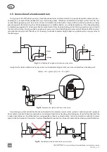
the unit with a siphon. Due to positive or negative air pressure in the air handling unit, water cannot drain out of the conden-
sate collection tray by itself. Therefore, it is necessary to connect a proper height siphon or a siphon with a one-way valve to
the drain pipe.
p < 0
p > 0
H mm
H mm
H/2 mm
Ø
40 m
m
Ø
40 m
m
Fig. 23.
Installation of a siphon without a one-way valve
Height
H
of a siphon without a one-way valve is selected according to static pressure
p
inside the air handling unit:
H [mm] = 25 + p [mm H
2
O] = 25 + 0.1 x p [Pa]
Ø
40 m
m
Fig. 24.
Example of a siphon with a one-way valve
Any drainage system cannot be directly connected to the common waste water system in order to protect supply air
from contamination with bacteria and odours. Condensate from the air handling unit drainage system shall be collected into
a separate container or should be lead to a sewage grille without any direct contact: do not connect drain directly to sewer
pipe and do not immerse it into water. Condensate collection location must be easily accessible for cleaning and disinfection.
Fig. 25.
Condensate drain connection to sewer system


