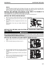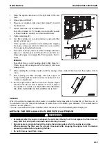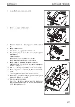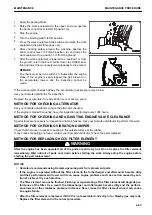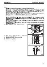
10. Extend and retract each of the steering, bucket, and boom
cylinders to the stroke end 3 to 4 times.
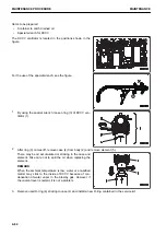
11. Stop the engine, then loosen air bleeding plug (7).
12. After bleeding air from the hydraulic tank, tighten plug (7).
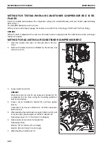
13. Bleed air while running the engine at low idle.
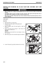
14. Check the hydraulic oil level oil level.
Check that the hydraulic oil is at the specified level. For
details, see “METHOD FOR CHECKING OIL LEVEL IN
HYDRAULIC TANK, ADDING OIL (4-42)”.
15. Increase the engine speed and bleed air according to step
9.
Repeat this work until no air is discharged from plug (7).
16. After bleeding air, tighten plug (7).
Tightening torque: 11.3±1.5 Nm {1.15±0.15 kgm}
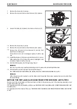
17. Check the hydraulic oil level.
Check that the hydraulic oil is at the specified level. For details, see “METHOD FOR CHECKING OIL LEV-
EL IN HYDRAULIC TANK, ADDING OIL (4-42)”.
18. Check the filter cover mount for oil leakage.
19. Install cover (1).
METHOD FOR REPLACING HYDRAULIC TANK BREATHER ELEMENT
k
k
WARNING
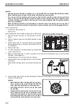
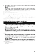
• Immediately after the engine is stopped, its parts and oil are still very hot and may cause burn in-
jury. Wait for the temperature to go down, and then start the work.
• When removing the oil filler cap, the oil may spout out. Turn it slowly to release the internal pres-
sure, then remove it carefully.
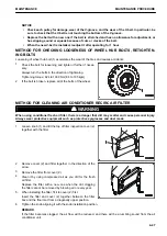
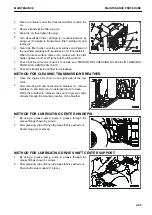
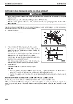
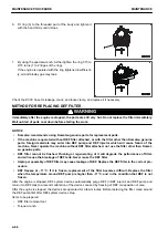
1.
Before removing the breather, wipe off dirt and dusts
around it.
2.
Loosen the bolts and remove the cover.
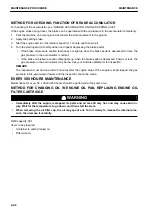
3.
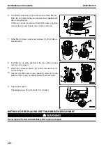
Remove the cap of oil filler port (F).
4.
Remove snap ring (2) of breather (1), remove breather cap
(3), and replace filter element (4) with a new one.
5.
Install breather cap (3) and snap ring (2).
6.
Close the cap of oil filler port (F).
MAINTENANCE
MAINTENANCE PROCEDURE
4-59
Содержание WA480-8
Страница 2: ......
Страница 19: ...Distributor name Address Phone Fax Service personnel FOREWORD PRODUCT INFORMATION 1 17...
Страница 29: ...LOCATION OF SAFETY LABELS SAFETY SAFETY LABELS 2 3...
Страница 69: ...OPERATION Please read and make sure that you understand the SAFETY section before reading this section 3 1...
Страница 76: ...Outside of cab 1 Slow blow fuse 2 Dust indicator 3 Articulation lock pin 4 Toolbox GENERAL VIEW OPERATION 3 8...
Страница 159: ...SWITCHES 1 ECSS switch 2 Front working lamp switch OPERATION EXPLANATION OF COMPONENTS 3 91...
Страница 302: ...Securing position Fixing angle A 61 B 53 C 33 D 38 TRANSPORTATION OPERATION 3 234...
Страница 324: ......
Страница 325: ...MAINTENANCE Please read and make sure that you understand the SAFETY section before reading this section 4 1...
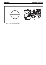
Страница 397: ...Viewed from the rear side of the machine MAINTENANCE MAINTENANCE PROCEDURE 4 73...
Страница 402: ......
Страница 403: ...SPECIFICATIONS 5 1...
Страница 405: ...1 Value when bucket dump angle is 45 B I A G E H F D C 9 J W0 1 4 5 6 SPECIFICATIONS SPECIFICATIONS 5 3...
Страница 406: ......
Страница 422: ......
Страница 423: ...REPLACEMENT PARTS 7 1...
Страница 439: ......
Страница 440: ...WA480 8 WHEEL LOADER Form No VENAM51500 2018 KOMATSU All Rights Reserved Printed in Europe 07 2018...

