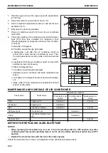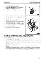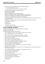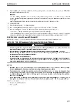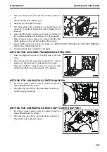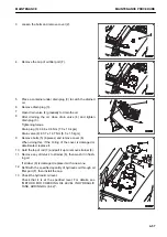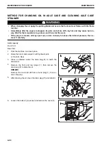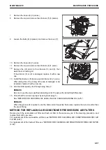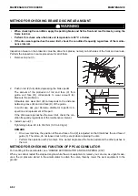
METHOD FOR CHECKING FUNCTION OF BRAKE ACCUMULATOR
For handling of the accumulator, see “HANDLE ACCUMULATOR AND GAS SPRING (2-39)”.
If the engine stops during travel, the brake can be operated with the oil pressure in the accumulator temporarily.
1.
Park the machine on a level ground and lower the work equipment to the ground.
2.
Apply the parking brake.
3.
Start the engine and run it at medium speed for 1 minute and then stop it.
4.
Turn the starting switch to ON position and repeat depressing the brake pedal.
• If the brake oil pressure caution lamp does not light up when the brake pedal is depressed 6 times, the
gas pressure in the accumulator is normal.
• If the brake oil pressure caution lamp lights up when the brake pedal is depressed 5 times or less, the
gas pressure in the accumulator may be low. Ask your Komatsu distributor for inspection.
REMARK
The inspection must be done within 5 minutes after the engine stops. If the engine is kept stopped, the gas
pressure in the accumulator lowers and the inspection cannot be made.
EVERY 500 HOURS MAINTENANCE
Maintenance for every 50, 100 and 250 hours should be performed at the same time.
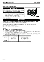
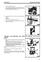
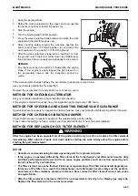
METHOD FOR CHANGING OIL IN ENGINE OIL PAN, REPLACING ENGINE OIL
FILTER CARTRIDGE
k
k
WARNING
• Immediately after the engine is stopped, its parts and oil are still very hot, and may cause burn in-
jury. Wait for the temperature to go down, and then start the work.
• When removing the oil filler cap, the oil may spout out. Turn it slowly to release the internal pres-
sure, then remove it carefully.
Refill capacity: 38 ℓ
Items to be prepared
• Container to catch drained oil
• Filter wrench
MAINTENANCE PROCEDURE
MAINTENANCE
4-48
Содержание WA480-8
Страница 2: ......
Страница 19: ...Distributor name Address Phone Fax Service personnel FOREWORD PRODUCT INFORMATION 1 17...
Страница 29: ...LOCATION OF SAFETY LABELS SAFETY SAFETY LABELS 2 3...
Страница 69: ...OPERATION Please read and make sure that you understand the SAFETY section before reading this section 3 1...
Страница 76: ...Outside of cab 1 Slow blow fuse 2 Dust indicator 3 Articulation lock pin 4 Toolbox GENERAL VIEW OPERATION 3 8...
Страница 159: ...SWITCHES 1 ECSS switch 2 Front working lamp switch OPERATION EXPLANATION OF COMPONENTS 3 91...
Страница 302: ...Securing position Fixing angle A 61 B 53 C 33 D 38 TRANSPORTATION OPERATION 3 234...
Страница 324: ......
Страница 325: ...MAINTENANCE Please read and make sure that you understand the SAFETY section before reading this section 4 1...
Страница 397: ...Viewed from the rear side of the machine MAINTENANCE MAINTENANCE PROCEDURE 4 73...
Страница 402: ......
Страница 403: ...SPECIFICATIONS 5 1...
Страница 405: ...1 Value when bucket dump angle is 45 B I A G E H F D C 9 J W0 1 4 5 6 SPECIFICATIONS SPECIFICATIONS 5 3...
Страница 406: ......
Страница 422: ......
Страница 423: ...REPLACEMENT PARTS 7 1...
Страница 439: ......
Страница 440: ...WA480 8 WHEEL LOADER Form No VENAM51500 2018 KOMATSU All Rights Reserved Printed in Europe 07 2018...

