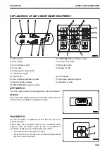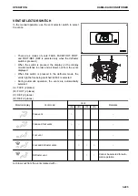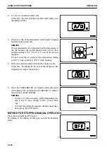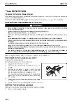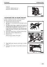
AUTO SWITCH
Use auto switch for automatic selection of the air flow and
vents according to the set temperature.
This switch is also used as the main switch of the air condition-
er.
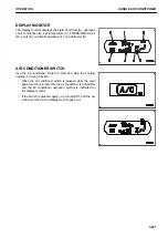
• When AUTO switch is pressed, AUTO on the display moni-
tor lights up to indicate that the air conditioner is in the au-
tomatic mode.
• When switching from automatic operation to manual oper-
ation, it is possible to use the switches to select the air flow
and vents.
At this time, AUTO on the display monitor goes out.
• When clearing the window mist at low temperature, use
the defroster switch.
REMARK
Do not leave the door open for a long time (3 minutes or lon-
ger) while air conditioner is working.
The automatic air conditioner controls the air automatically ac-
cording to the environment.
If the environment changed suddenly by leaving cab door open
for a long time, etc., the control of air conditioner may change
temporarily, but this is not a failure.
Even if the control changes, it returns automatically to control
the air according to the environment after certain period of time
elapses.
FRESH/RECIRC AIR SELECTOR SWITCH
Use FRESH/RECIRC air selector switch to switch the air
source between recirculation of the air inside the cab and in-
take of fresh air from the outside.
• In the fresh air mode, (A) is lit on the display monitor.
• In the recirculation air mode, (B) is lit on the display moni-
tor.
RECIRC
• Only the air inside the cab is circulated. Use this setting to
perform quick cooling or heating of the cab or when out-
side air is dirty.
FRESH
• Outside air is taken into the cab. Use this position to make
the air inside the cab fresh or to remove the mist from the
cab windows.
HANDLE AIR CONDITIONER
OPERATION
3-226
Содержание WA480-8
Страница 2: ......
Страница 19: ...Distributor name Address Phone Fax Service personnel FOREWORD PRODUCT INFORMATION 1 17...
Страница 29: ...LOCATION OF SAFETY LABELS SAFETY SAFETY LABELS 2 3...
Страница 69: ...OPERATION Please read and make sure that you understand the SAFETY section before reading this section 3 1...
Страница 76: ...Outside of cab 1 Slow blow fuse 2 Dust indicator 3 Articulation lock pin 4 Toolbox GENERAL VIEW OPERATION 3 8...
Страница 159: ...SWITCHES 1 ECSS switch 2 Front working lamp switch OPERATION EXPLANATION OF COMPONENTS 3 91...
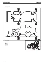
Страница 302: ...Securing position Fixing angle A 61 B 53 C 33 D 38 TRANSPORTATION OPERATION 3 234...
Страница 324: ......
Страница 325: ...MAINTENANCE Please read and make sure that you understand the SAFETY section before reading this section 4 1...
Страница 397: ...Viewed from the rear side of the machine MAINTENANCE MAINTENANCE PROCEDURE 4 73...
Страница 402: ......
Страница 403: ...SPECIFICATIONS 5 1...
Страница 405: ...1 Value when bucket dump angle is 45 B I A G E H F D C 9 J W0 1 4 5 6 SPECIFICATIONS SPECIFICATIONS 5 3...
Страница 406: ......
Страница 422: ......
Страница 423: ...REPLACEMENT PARTS 7 1...
Страница 439: ......
Страница 440: ...WA480 8 WHEEL LOADER Form No VENAM51500 2018 KOMATSU All Rights Reserved Printed in Europe 07 2018...


