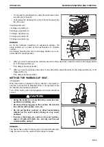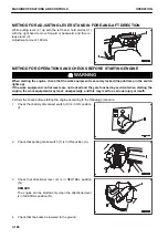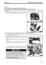
• To increase the damping force, direct the knob toward bot-
tom side (A) of the seat.
• To decrease the damping force, direct the knob toward top
(B) of the seat.
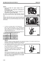
Adjustment amount
1st stage: at position (c)
2nd stage: at position (d)
3rd stage: at position (e)
4th stage: at position (f)
5th stage: at position (g)
REMARK
As for the hardness adjustment of suspension damper, 3rd
stage position (e) is preset as the best position for operator
comfort.
Accordingly, adjusting the knob to 3rd stage position (e) is rec-
ommended for usual operation.
1.
When you want to decrease the vertical movement of the suspension, adjust the knob to 4th stage position
(f) or 5th stage position (g).
(The damper becomes harder.)
2.
When you want to decrease the shock to the seat further, adjust the knob to 2nd stage position (d) or 1st
stage position (c).
(The damper becomes softer.)
METHOD FOR WARMING UP SEAT
(if equipped)
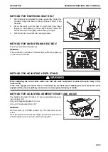
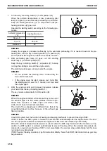
When the switch is operated in the (A) direction, the heater in-
side the seat cushion is activated. When it is operated in the
(B) direction, the heater is turned off.
Turn off the switch when the temperature of cushion becomes
correct.
k
k
CAUTION
• Using the heater for a long time may cause low tem-
perature burn (blister, etc.).
• Do not put heavy luggage on the cushion. Do not stick
the cushion with needles, nails, etc.
• Do not put blanket, cushion, or other heat-retaining
material on the seat cushion. Doing so may cause
overheat.
• If water or beverage, etc. spills on the seat cushion,
wipe it off with soft cloth, etc., and dry out the seat
cushion before using it.
REMARK
The heater has no timer function and is not turned off automati-
cally. Be sure to turn the switch off after using the heater.
OPERATION
MACHINE OPERATIONS AND CONTROLS
3-173
Содержание WA480-8
Страница 2: ......
Страница 19: ...Distributor name Address Phone Fax Service personnel FOREWORD PRODUCT INFORMATION 1 17...
Страница 29: ...LOCATION OF SAFETY LABELS SAFETY SAFETY LABELS 2 3...
Страница 69: ...OPERATION Please read and make sure that you understand the SAFETY section before reading this section 3 1...
Страница 76: ...Outside of cab 1 Slow blow fuse 2 Dust indicator 3 Articulation lock pin 4 Toolbox GENERAL VIEW OPERATION 3 8...
Страница 159: ...SWITCHES 1 ECSS switch 2 Front working lamp switch OPERATION EXPLANATION OF COMPONENTS 3 91...
Страница 302: ...Securing position Fixing angle A 61 B 53 C 33 D 38 TRANSPORTATION OPERATION 3 234...
Страница 324: ......
Страница 325: ...MAINTENANCE Please read and make sure that you understand the SAFETY section before reading this section 4 1...
Страница 397: ...Viewed from the rear side of the machine MAINTENANCE MAINTENANCE PROCEDURE 4 73...
Страница 402: ......
Страница 403: ...SPECIFICATIONS 5 1...
Страница 405: ...1 Value when bucket dump angle is 45 B I A G E H F D C 9 J W0 1 4 5 6 SPECIFICATIONS SPECIFICATIONS 5 3...
Страница 406: ......
Страница 422: ......
Страница 423: ...REPLACEMENT PARTS 7 1...
Страница 439: ......
Страница 440: ...WA480 8 WHEEL LOADER Form No VENAM51500 2018 KOMATSU All Rights Reserved Printed in Europe 07 2018...

