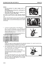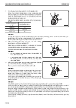
3.
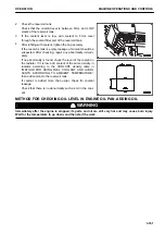
When the machine is equipped with the secondary steer-
ing, it performs self check approximately 3 seconds after
the starting switch is turned to ON position.
At this time, the steering oil pressure caution lamp (red)
and the secondary steering pilot lamp light up simultane-
ously.
If the machine does not perform the self check or the
above lamps do not light up, there may be a failure. Ask
your Komatsu distributor for inspection.
Check of the secondary steering is not performed in the following cases.
• When you have turned the starting switch to ON position and, without starting the engine, turned it to OFF
position then turned it to ON position again.
• When you have turned the starting switch to ON position again immediately after the engine is stopped
when the steering pressure is not completely lowered.
• When the engine preheating is in operation.
METHOD FOR CHECKING HORN
Operate the horn switch and check that the horn sounds.
If there is any abnormality, ask your KOMATSU distributor for testing and repair.
METHOD FOR CHECKING DEFROSTER FUNCTION
• Operate the air conditioner and check that the air flows out of the vents properly onto the front glass.
If there is any abnormality, ask your KOMATSU distributor for testing and repair.
• Operate the rear heated wire glass switch and check that the rear glass surface is heated properly.
If there is any abnormality, ask your KOMATSU distributor for testing and repair.
METHOD FOR CHECKING LOCKS
Check that all places can be locked properly.
(For the locations of the locks, see “LOCK (3-218)”.)
If there is any abnormality, ask your KOMATSU distributor for testing and repair.
METHOD FOR CHECKING ALTERNATE EXIT OF CAB
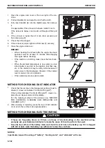
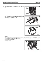
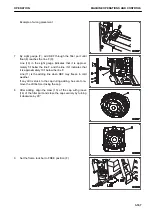
Operate the open knob for alternate exit of cab, and check that the exit opens and closes properly.
If there is any abnormality, ask your KOMATSU distributor for testing and repair.
METHOD FOR ADJUSTING
METHOD FOR ADJUSTING OPERATOR'S SEAT
k
k
WARNING
• Place the machine in a safe place when adjusting the position of the operator's seat.
Always set the work equipment lock lever to LOCK position (the pilot lamp in the switch is lit) to
prevent any accidental contact with the control levers.
• Adjust it before starting operation or when operators change shift.
• Adjust the position of the operator's seat so that you can depress the brake pedal fully with your
back against the seat backrest.
OPERATION
MACHINE OPERATIONS AND CONTROLS
3-169
Содержание WA480-8
Страница 2: ......
Страница 19: ...Distributor name Address Phone Fax Service personnel FOREWORD PRODUCT INFORMATION 1 17...
Страница 29: ...LOCATION OF SAFETY LABELS SAFETY SAFETY LABELS 2 3...
Страница 69: ...OPERATION Please read and make sure that you understand the SAFETY section before reading this section 3 1...
Страница 76: ...Outside of cab 1 Slow blow fuse 2 Dust indicator 3 Articulation lock pin 4 Toolbox GENERAL VIEW OPERATION 3 8...
Страница 159: ...SWITCHES 1 ECSS switch 2 Front working lamp switch OPERATION EXPLANATION OF COMPONENTS 3 91...
Страница 302: ...Securing position Fixing angle A 61 B 53 C 33 D 38 TRANSPORTATION OPERATION 3 234...
Страница 324: ......
Страница 325: ...MAINTENANCE Please read and make sure that you understand the SAFETY section before reading this section 4 1...
Страница 397: ...Viewed from the rear side of the machine MAINTENANCE MAINTENANCE PROCEDURE 4 73...
Страница 402: ......
Страница 403: ...SPECIFICATIONS 5 1...
Страница 405: ...1 Value when bucket dump angle is 45 B I A G E H F D C 9 J W0 1 4 5 6 SPECIFICATIONS SPECIFICATIONS 5 3...
Страница 406: ......
Страница 422: ......
Страница 423: ...REPLACEMENT PARTS 7 1...
Страница 439: ......
Страница 440: ...WA480 8 WHEEL LOADER Form No VENAM51500 2018 KOMATSU All Rights Reserved Printed in Europe 07 2018...


