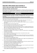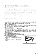
REMARK
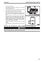
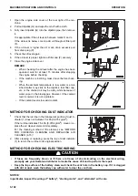
If drain plug (2) is hard to run, apply grease to O-ring (5) of
plug (2) according to the following procedure.
1) Place a container under drain hose (4) to catch the
drained fuel.
2) Loosen plug (2) and drain all the fuel and sediment
through drain hose (4).
3) Check that nothing more comes out from drain hose
(4), then remove plug (2).
4) Apply a suitable amount of grease to O-ring (5). At this
time, take care that grease will not stick to water drain
port (a) and threaded portion of the plug.
5) Tighten plug (2) by hand until it stops.
6) Remove the container for catching the drained fuel.
• If transparent cup (3) is so dirty that the inside
cannot be seen, clean it when replacing the filter.
• In the case that the plug (2) has been removed
during the cleaning work, apply grease to O-ring
(5) and tighten with your finger until it stops.
METHOD FOR CHECKING COOLANT LEVEL, ADDING COOLANT
k
k
WARNING
• Do not open the radiator cap unless necessary. When checking the coolant level, check the reser-
voir tank when the engine is cold.
• Immediately after the engine is stopped, the coolant is at high temperature. And the pressure is still
accumulated in the radiator. If the cap is removed in this condition, it is dangerous that you may get
burn injury. Always wait for the temperature to go down, and turn the cap slowly to release the pres-
sure.
k
k
CAUTION
When refilling with coolant, support you body securely by using the step and handrail provided.
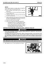
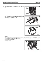
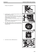
1.
Open platform cover (1) on the right side of the machine.
MACHINE OPERATIONS AND CONTROLS
OPERATION
3-160
Содержание WA480-8
Страница 2: ......
Страница 19: ...Distributor name Address Phone Fax Service personnel FOREWORD PRODUCT INFORMATION 1 17...
Страница 29: ...LOCATION OF SAFETY LABELS SAFETY SAFETY LABELS 2 3...
Страница 69: ...OPERATION Please read and make sure that you understand the SAFETY section before reading this section 3 1...
Страница 76: ...Outside of cab 1 Slow blow fuse 2 Dust indicator 3 Articulation lock pin 4 Toolbox GENERAL VIEW OPERATION 3 8...
Страница 159: ...SWITCHES 1 ECSS switch 2 Front working lamp switch OPERATION EXPLANATION OF COMPONENTS 3 91...
Страница 302: ...Securing position Fixing angle A 61 B 53 C 33 D 38 TRANSPORTATION OPERATION 3 234...
Страница 324: ......
Страница 325: ...MAINTENANCE Please read and make sure that you understand the SAFETY section before reading this section 4 1...
Страница 397: ...Viewed from the rear side of the machine MAINTENANCE MAINTENANCE PROCEDURE 4 73...
Страница 402: ......
Страница 403: ...SPECIFICATIONS 5 1...
Страница 405: ...1 Value when bucket dump angle is 45 B I A G E H F D C 9 J W0 1 4 5 6 SPECIFICATIONS SPECIFICATIONS 5 3...
Страница 406: ......
Страница 422: ......
Страница 423: ...REPLACEMENT PARTS 7 1...
Страница 439: ......
Страница 440: ...WA480 8 WHEEL LOADER Form No VENAM51500 2018 KOMATSU All Rights Reserved Printed in Europe 07 2018...

