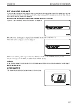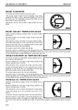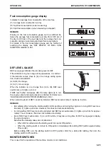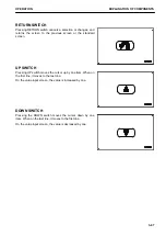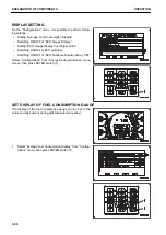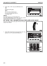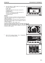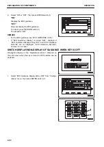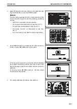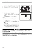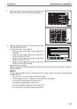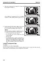
(4) RETURN switch
Cancels a selection or changes, and returns to the previous screen or the standard screen.
REMARK
• If no switch is operated for 30 seconds on the user menu screen, the screen automatically returns to the
previous screen or the standard screen.
• The user menu screen is displayed only while the machine is stopped completely.
• If the machine travels while the user menu screen is displayed, the screen automatically returns to the
standard screen.
REMARK
The default tab when the standard screen is changed to the user menu screen varies with the machine condi-
tion.
1. SCR event occurs → “SCR Information”
2. KDPF event occurs → “Aftertreatment Devices Regeneration”
3. Hydraulic fan is rotating in reverse → “Machine Setting and Information”
4. Maintenance caution occurs → “Maintenance”
5. Message is not read yet → Message display
6. Other than 1 to 5 → “Energy Saving Guidance”
* If multiple conditions are established simultaneously, the above priority is given.
ENERGY SAVING GUIDANCE
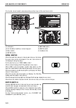
Each item of “Energy Saving Guidance” menu (A) is used for
displaying and setting the notification relevant to energy saving.
• “Operation Records”
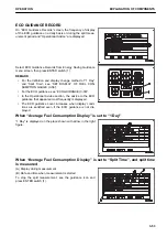
• “Eco Guidance Records”
• “Average Fuel Consumption Record”
• “Configurations”
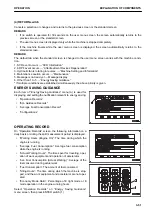
OPERATING RECORD
On “Operation Records” screen, the following information on a
daily basis or during the split measurement period is displayed.
• “Working Hours (Engine On)”: The time during which the
engine is running
• “Average Fuel Consumption”: Average fuel consumption
while the engine is running
• “Actual Working Hours”: The time spent for traveling, oper-
ation of work equipment and operation of accelerator
• “Ave Fuel Consumption (Actual Working)”: Average of the
fuel consumed during actual work
• “Fuel Consumption”: The amount of fuel consumed
• “Idling Hours”: The time during which the machine is stop-
ped, and the work equipment and accelerator are not oper-
ated
• “Economy Mode Ratio”: Percentage of E light mode or E
mode operation in the engine-running hours
Select “Operation Records” on “Energy Saving Guidance”
menu screen, then press ENTER switch (1).
OPERATION
EXPLANATION OF COMPONENTS
3-51
Содержание WA480-8
Страница 2: ......
Страница 19: ...Distributor name Address Phone Fax Service personnel FOREWORD PRODUCT INFORMATION 1 17...
Страница 29: ...LOCATION OF SAFETY LABELS SAFETY SAFETY LABELS 2 3...
Страница 69: ...OPERATION Please read and make sure that you understand the SAFETY section before reading this section 3 1...
Страница 76: ...Outside of cab 1 Slow blow fuse 2 Dust indicator 3 Articulation lock pin 4 Toolbox GENERAL VIEW OPERATION 3 8...
Страница 159: ...SWITCHES 1 ECSS switch 2 Front working lamp switch OPERATION EXPLANATION OF COMPONENTS 3 91...
Страница 302: ...Securing position Fixing angle A 61 B 53 C 33 D 38 TRANSPORTATION OPERATION 3 234...
Страница 324: ......
Страница 325: ...MAINTENANCE Please read and make sure that you understand the SAFETY section before reading this section 4 1...
Страница 397: ...Viewed from the rear side of the machine MAINTENANCE MAINTENANCE PROCEDURE 4 73...
Страница 402: ......
Страница 403: ...SPECIFICATIONS 5 1...
Страница 405: ...1 Value when bucket dump angle is 45 B I A G E H F D C 9 J W0 1 4 5 6 SPECIFICATIONS SPECIFICATIONS 5 3...
Страница 406: ......
Страница 422: ......
Страница 423: ...REPLACEMENT PARTS 7 1...
Страница 439: ......
Страница 440: ...WA480 8 WHEEL LOADER Form No VENAM51500 2018 KOMATSU All Rights Reserved Printed in Europe 07 2018...

