SAFETY LOCKS
52
3.1 SAFETY LOCKS
DANGER
q
If it is necessary to stop the machine with raised loader arm, always engage the mechanical safety lock
on the arm and lock the equipment and travel control by lifting the safety bars (see "3.3.5 pos. 1 - SA-
FETY BARS").
q
When travelling on roads with a machine homologated for this purpose, lower the loader arm complete-
ly, engage the bucket antirotation lock, apply the teeth guard and lock the equipment control by shifting
the safety device lever to the lock position.
q
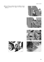
When travelling on roads with a machine homologated for this purpose and equipped with excavator,
fold the bucket completely, apply the lock between boom and arm, the antirotation lock between boom
and sliding plate and the centre lock of the sliding plate.
Raise the stabilizer supports completely, couple the relevant safety chains and finally lock the equip-
ment control by shifting the safety device lever to the lock position. If the machine is also equipped with
rear stabilizers, raise the supports and lock them with the relevant safety chains.
q
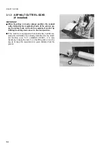
When travelling on roads with a machine homologated for this purpose and equipped with asphalt cut-
ter, apply the lock on the lifting jack in order to keep the equipment at a given distance from the ground,
lower the loader arm completely, install the antirotation lock of the front equipment and finally lock the
equipment control by shifting the safety device lever to the lock position.
q
Non-compliance with these rules may lead to serious accidents.
3.1.1 LOADER LOCKS
q
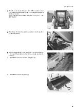
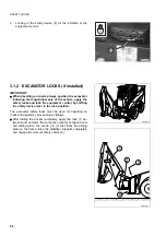
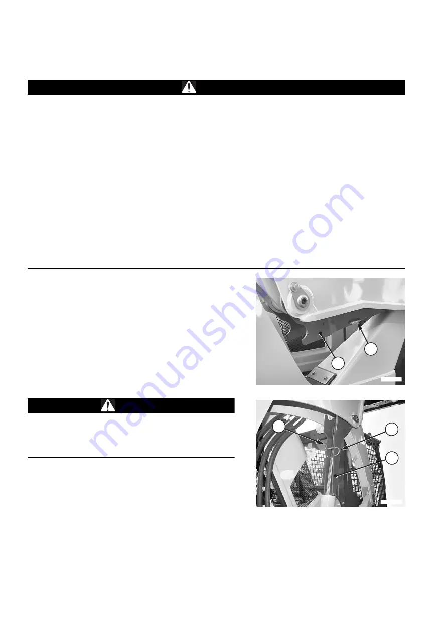
The loader arm is provided with a safety lock (1) to be used
to keep the arm raised when the machine is serviced or rou-
tine operations are carried out.
q
The engagement of the safety lock must be carried out by
two persons, one seated in driving position to check the
movements of the machine and the other standing on the
ground to engage the lock correctly.
q
It is important to remember that in operating conditions the
safety lock (1) must be positioned against the arm and kept
in this position by means of the safety pin (2).
DANGER
q
After engaging the lock (1), fasten it with the safety pin
(2) held by the split pin (3).
q
Do not carry out any operation under the raised loader
arm if the safety lock (1) has not been engaged.
IMPORTANT
q
Always open the engine hood (see "3.5.1 ENGINE
HOOD") before lifting the loader arm.
q
The safety lock must always adhere to the hydraulic cyl-
inder rod.
q
The safety lock must be brought to its definitive position
by moving the contact surfaces slowly and continuous-
ly, in such a way as not to damage the cylinder head sur-
face.
1
2
RKAB1080
1
2
RKAB1090
3
Содержание SK820-5 turbo
Страница 2: ......
Страница 17: ...SAFETY AND ACCIDENT PREVENTION 15...
Страница 19: ...SAFETY NOISE AND VIBRATION PLATES 17 RWA00010 RWA37020...
Страница 21: ...SAFETY NOISE AND VIBRATION PLATES 19 RWA37040 RWA00010 RWA00020...
Страница 53: ...THE MACHINE AND ITS OPERATIONS 51...
Страница 62: ...GENERAL VIEWS 60 10 Left console switches 11 Right console switches RWAA9720 11 RWAA11260 10...
Страница 154: ...152 PAGE INTENTIONALLY LEFT BLANK...
Страница 155: ...MAINTENANCE 153...
Страница 205: ...TECHNICAL SPECIFICATIONS 203...
Страница 211: ...TECHNICAL DATA 209 OVERALL DIMENSIONS WITH GRAPPLE FORK RWA36900 1070 2250 1060 1320 3450 180 1670 1460 1380...
Страница 213: ...TECHNICAL DATA 211 SOLID TYRES SIZE MAKE 10x16 5 AIR BOSS...
Страница 214: ...212 PAGE INTENTIONALLY LEFT BLANK...
Страница 215: ...AUTHORISED OPTIONAL EQUIPMENT 213...
Страница 242: ...240 PAGE INTENTIONALLY LEFT BLANK...
Страница 243: ......
Страница 244: ...2004 KOMATSU UTILITY EUROPE S p A All Rights Reserved Printed in Europe...

