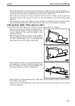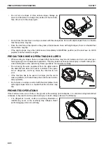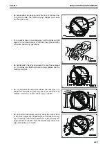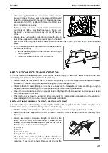
STABILITY
• When dismantling or assembling the machine for the purpose of maintenance, repair or transportation, al-
ways ensure that at each stage of the process, care is taken to ensure that the machine remains stable.
Failure to do this could result in serious injury or death.
GUARDS
• Guards are installed in the area of the engine to protect personnel from moving parts. These guards should
only be removed by Komatsu service engineer unless specific instructions are given in this manual.
END OF SERVICE LIFE
• For safe dismantling of the machine at the end of service life, please contact your Komatsu distributor.
STOP ENGINE BEFORE CARRYING OUT INSPECTION AND MAINTENANCE
If you are caught or pinched between the work equipment during operation, or exposed to high-temperature or
high-pressure liquids, it is dangerous and may cause serious personal injury or death. Always observe the fol-
lowing.
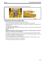
• Lower the work equipment to the ground and stop the en-
gine before performing any inspection and maintenance.
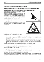
• Turn the starting switch to ON position. Operate the work
equipment control lever back and forth, right and left a few
times fully to release the remaining internal pressure in the
hydraulic circuit. Then move lock lever (1) to LOCK posi-
tion (L) and turn the starting switch to OFF position.
• Check that the battery relay is off and main power is not
conducted. (After turning the starting switch to OFF posi-
tion, wait for approximately 1 minute and press the horn
switch. If the horn does not sound, power is not conduct-
ed.)
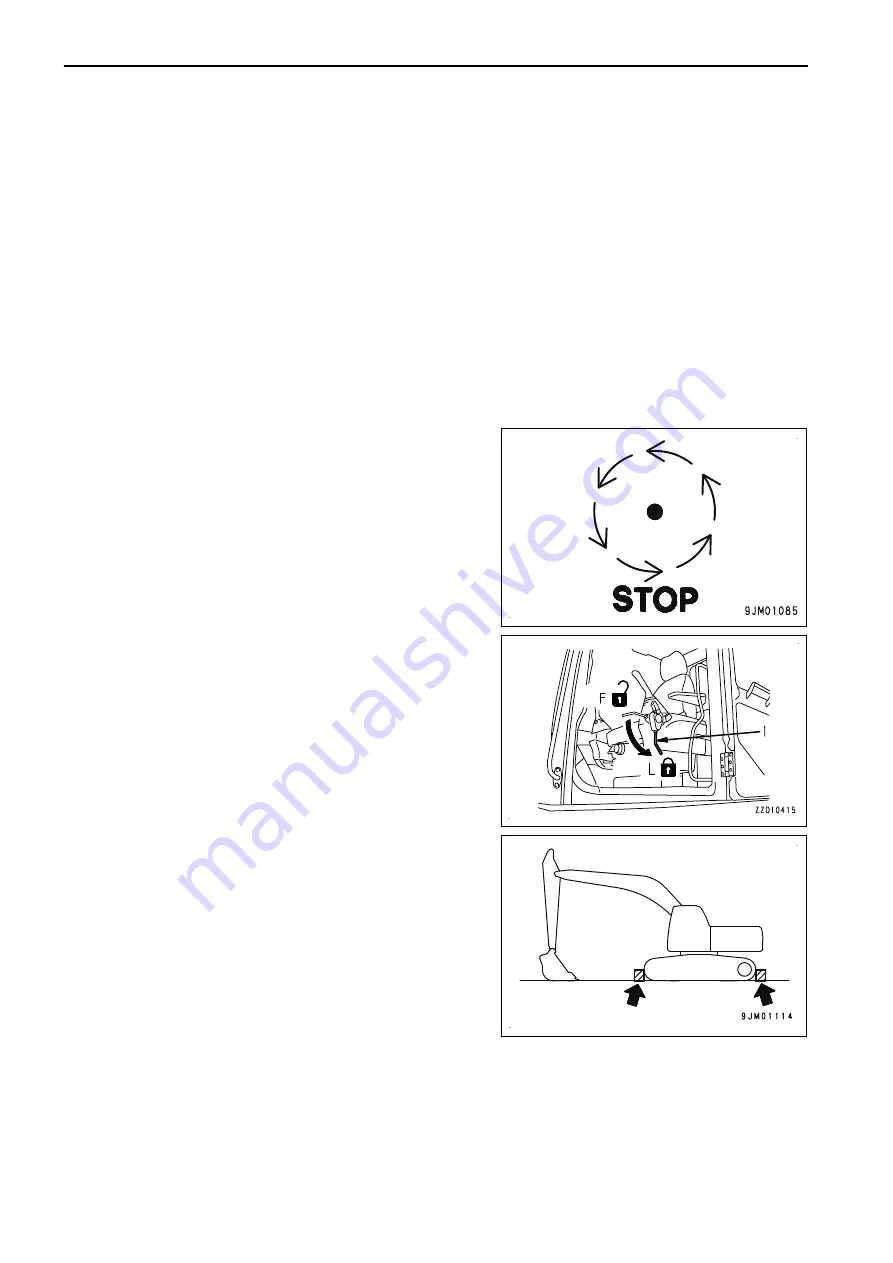
• Block the tracks from movement.
TWO WORKERS FOR MAINTENANCE WHEN ENGINE IS RUNNING
To prevent accident, do not perform maintenance with the engine running. When it is necessary to perform the
maintenance with the engine running, always observe the following.
• One worker must always sit on the operator's seat and be ready to stop the engine at any time. All workers
must maintain contact with the other workers.
PRECAUTIONS FOR MAINTENANCE
SAFETY
2-36
Содержание PC700LC-11
Страница 2: ......
Страница 23: ...LOCATION OF SAFETY LABELS 5 SAFETY SAFETY LABELS 2 3...
Страница 66: ......
Страница 67: ...OPERATION Please read and make sure that you understand the SAFETY section before reading this section 3 1...
Страница 73: ...REMARK The above figure does not show all of the caution lamp symbols OPERATION GENERAL VIEW 3 7...
Страница 316: ......
Страница 317: ...MAINTENANCE Please read and make sure that you understand the SAFETY section before reading this section 4 1...
Страница 331: ...Fuel main fil ter cartridge Replace Replace Replace Replace MAINTENANCE MAINTENANCE SCHEDULE 4 15...
Страница 375: ...A Important inspection part F Front Revolving frame Center frame MAINTENANCE MAINTENANCE PROCEDURE 4 59...
Страница 396: ......
Страница 397: ...SPECIFICATIONS 5 1...
Страница 401: ...For 7 6m Boom SPECIFICATIONS SPECIFICATIONS 5 5...
Страница 402: ...SPECIFICATIONS SPECIFICATIONS 5 6...
Страница 426: ......
Страница 427: ...REPLACEMENT PARTS 7 1...
Страница 434: ......
Страница 442: ...PC700LC 11 HYDRAULIC EXCAVATOR Form No UENAM01321 2017 KOMATSU All Rights Reserved Printed in Belgium 09 2017...

