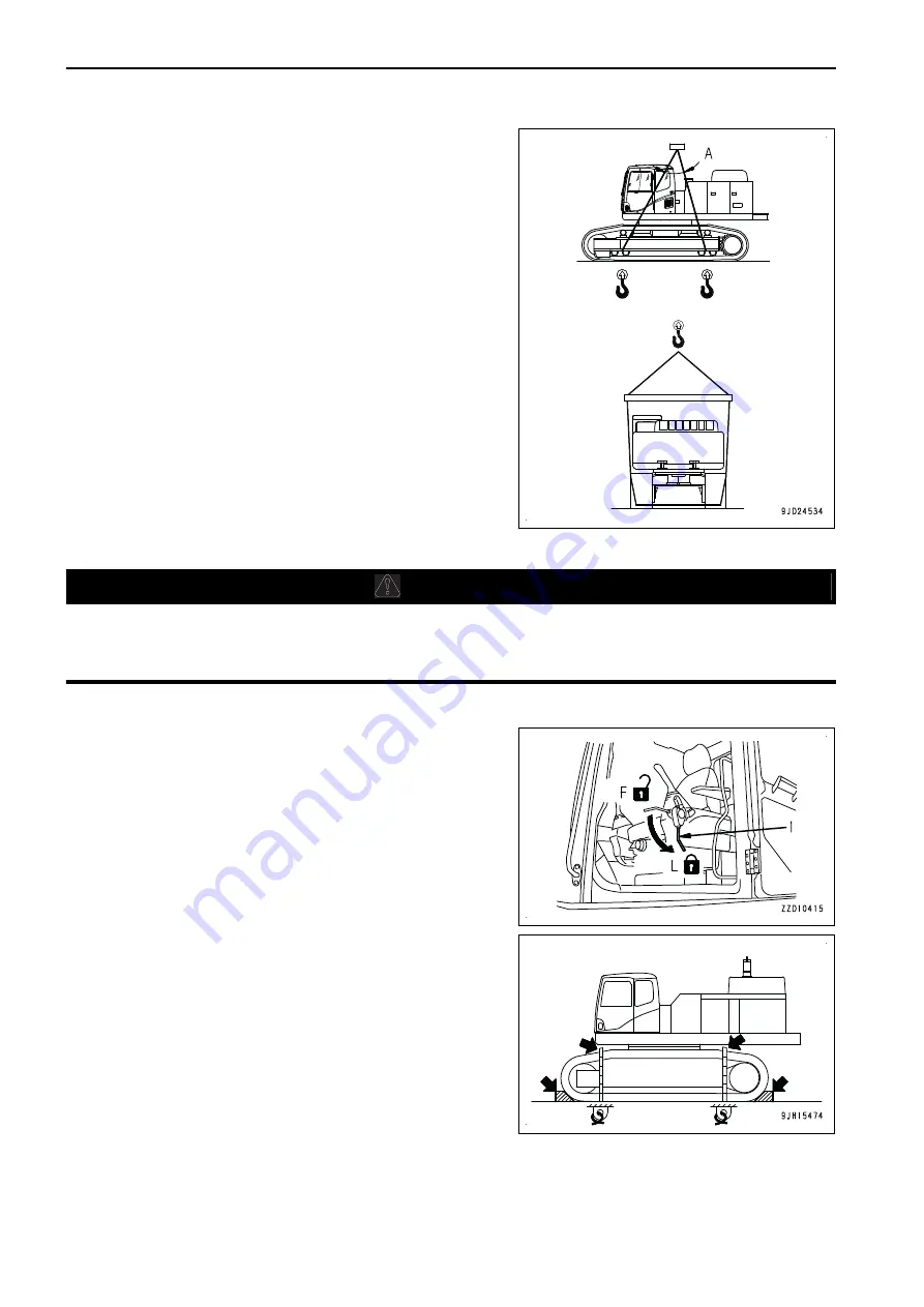
1.
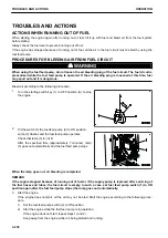
Pass the wire ropes between the 1st and 2nd track rollers
from the front and between the 1st and 2nd track rollers
from the rear.
For machines equipped with full roller guards for the track
rollers, pass the wire ropes under the tracks.
2.
The center of gravity mark put on the machine body indi-
cates the center of gravity when the machine is in the state
shown in the right figure.
3.
Set the lifting angle (A) of the wire rope to 30 to 40 °, then
sling the machine slowly.
4.
Stop slinging once soon after the machine is raised off the
ground, wait for the machine to be stable, and then sling it
again slowly.
PRECAUTIONS FOR LOADING MACHINE
k
k
WARNING
• Select a flat and firm ground for loading the machine.
Maintain a safe distance from the road shoulder.
• Run the engine at low speed, and drive the machine slowly.
After loading the machine in the specified position, secure it in place as follows.
1.
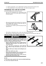
Set the lock lever (1) securely to LOCK position (L).
2.
Stop the engine, then remove the key from the starting
switch.
3.
Securely lock the glass window, ceiling window, front win-
dow, door of the operator's seat, side covers, engine hood,
and battery box cover.
4.
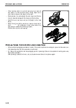
Prevent the machine from moving during transportation, by
putting wooden blocks on the front and rear sides of the
tracks, and secure the machine with chains or wire ropes
of suitable strength.
Fix the machine securely to prevent it from slipping side-
ways in particular.
MACHINE CONFIGURATION FOR TRANSPORTATION
The machine can be disassembled in three kits or in four kits for transportation. When transporting the machine,
ask your Komatsu distributor for disassembling.
TRANSPORTATION
OPERATION
3-226
Содержание PC700LC-11
Страница 2: ......
Страница 23: ...LOCATION OF SAFETY LABELS 5 SAFETY SAFETY LABELS 2 3...
Страница 66: ......
Страница 67: ...OPERATION Please read and make sure that you understand the SAFETY section before reading this section 3 1...
Страница 73: ...REMARK The above figure does not show all of the caution lamp symbols OPERATION GENERAL VIEW 3 7...
Страница 316: ......
Страница 317: ...MAINTENANCE Please read and make sure that you understand the SAFETY section before reading this section 4 1...
Страница 331: ...Fuel main fil ter cartridge Replace Replace Replace Replace MAINTENANCE MAINTENANCE SCHEDULE 4 15...
Страница 375: ...A Important inspection part F Front Revolving frame Center frame MAINTENANCE MAINTENANCE PROCEDURE 4 59...
Страница 396: ......
Страница 397: ...SPECIFICATIONS 5 1...
Страница 401: ...For 7 6m Boom SPECIFICATIONS SPECIFICATIONS 5 5...
Страница 402: ...SPECIFICATIONS SPECIFICATIONS 5 6...
Страница 426: ......
Страница 427: ...REPLACEMENT PARTS 7 1...
Страница 434: ......
Страница 442: ...PC700LC 11 HYDRAULIC EXCAVATOR Form No UENAM01321 2017 KOMATSU All Rights Reserved Printed in Belgium 09 2017...


