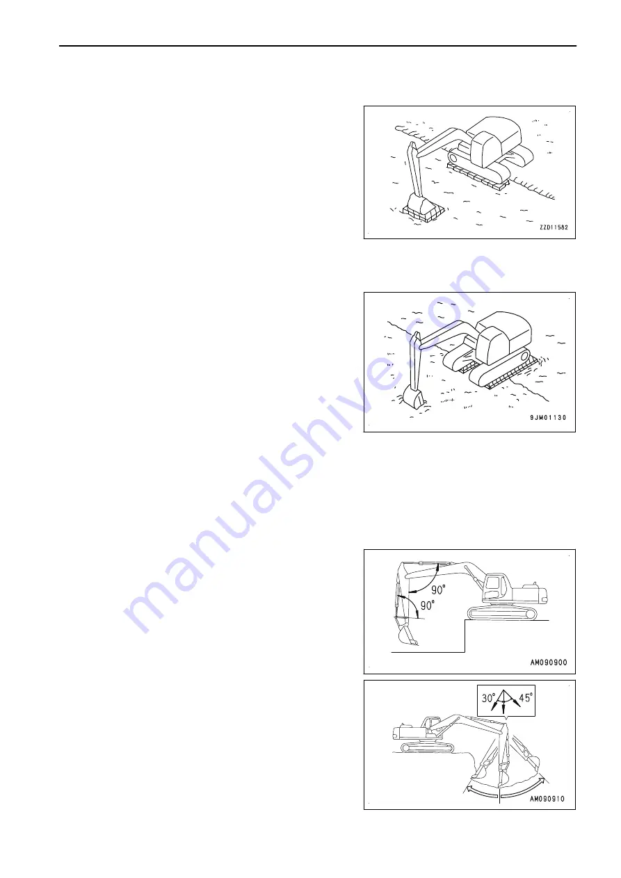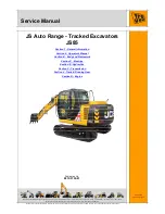
Track on one side stuck
NOTICE
When using the boom or arm to raise the machine, push
the ground by using the bottom of the bucket.
At this time, set the angle between the boom and the arm
at 90° to 110° and lower the bucket bottom surface to the
ground.
The same applies when using the bucket installed in the
reverse direction.
When only one side is stuck in mud, raise the track by lowering
the bucket to the ground on the stuck side. Lay boards or logs
under the raised track. Then raise the bucket and drive the ma-
chine out.
Tracks on both sides stuck
When the tracks on both sides get stuck and slip, lay logs,
wooden blocks, etc. according to the preceding procedure.
Stick the bucket into the front ground, pull in the arm as in dig-
ging operation, and set the travel lever to FORWARD position
to drive the machine out.
RECOMMENDED APPLICATIONS
In addition to the following, it is possible to further increase the range of applications by using various attach-
ments.
DIGGING WORK
BACKHOE WORK
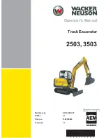
It is suitable for excavating areas that are lower than the machine.
When the condition of the machine is as shown in the figure
(angle between bucket cylinder and link, and between arm cyl-
inder and arm is 90 °), the maximum excavation force is ob-
tained from the pushing force of each cylinder.
When excavating, you can optimize your working efficiency by
using this angle effectively.
The range for excavating with the arm is from a 45 ° angle
away from the machine to a 30 ° angle towards the machine.
There may be some differences depending on the excavation
depth, but try to stay within the above range rather than operat-
ing the cylinder to the end of its stroke.
OPERATION
MACHINE OPERATIONS AND CONTROLS
3-195
Содержание PC700LC-11
Страница 2: ......
Страница 23: ...LOCATION OF SAFETY LABELS 5 SAFETY SAFETY LABELS 2 3...
Страница 66: ......
Страница 67: ...OPERATION Please read and make sure that you understand the SAFETY section before reading this section 3 1...
Страница 73: ...REMARK The above figure does not show all of the caution lamp symbols OPERATION GENERAL VIEW 3 7...
Страница 316: ......
Страница 317: ...MAINTENANCE Please read and make sure that you understand the SAFETY section before reading this section 4 1...
Страница 331: ...Fuel main fil ter cartridge Replace Replace Replace Replace MAINTENANCE MAINTENANCE SCHEDULE 4 15...
Страница 375: ...A Important inspection part F Front Revolving frame Center frame MAINTENANCE MAINTENANCE PROCEDURE 4 59...
Страница 396: ......
Страница 397: ...SPECIFICATIONS 5 1...
Страница 401: ...For 7 6m Boom SPECIFICATIONS SPECIFICATIONS 5 5...
Страница 402: ...SPECIFICATIONS SPECIFICATIONS 5 6...
Страница 426: ......
Страница 427: ...REPLACEMENT PARTS 7 1...
Страница 434: ......
Страница 442: ...PC700LC 11 HYDRAULIC EXCAVATOR Form No UENAM01321 2017 KOMATSU All Rights Reserved Printed in Belgium 09 2017...


