REMARK
• It is recommended to use a nozzle having a diameter and a length specified by ISO 22241-4 and an auto
stop function to add DEF. When the specified nozzle is used, the magnet installed inside the filler port of the
tank cancels the wrong fluid addition prevention device, and you can add DEF. This mechanism prevents
addition of DEF into the fuel tank, addition of fuel into DEF tank, and spill of DEF from the filler port.
• When using a nozzle which is not conformed to ISO 22241-4, hold it in your hand and add DEF carefully
while checking the sight gauge.
• Add only DEF in clearly marked DEF tanks that have the blue cap.
METHOD FOR CHECKING WORKING LAMP
Check that the working lamps and lamps inside the instruments light up properly. Check also that there is no dirt
or damage.
1.
Turn the starting switch to ON position.
2.
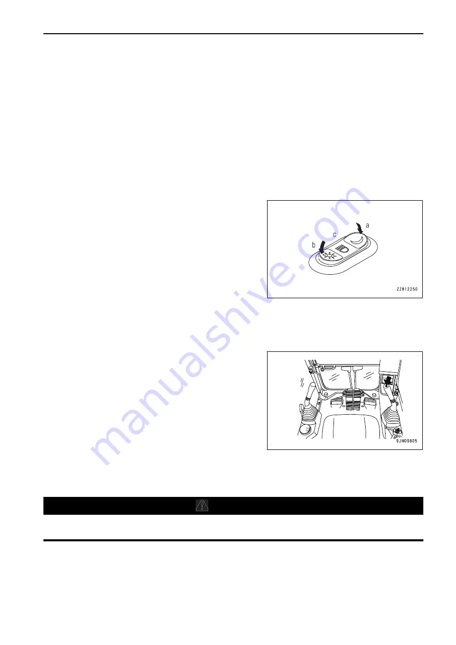
Check that the working lamp lights up properly when the
lamp switch is at night mode (a) and at day mode (b).
3.
After inspection, turn the lamp switch to OFF position (c),
and the working lamp goes out.
4.
After checking, turn the starting switch back to OFF posi-
tion.
If the lamps do not light up, a broken bulb or disconnected wire are the possible causes. Ask your Komatsu
distributor for repairs.
METHOD FOR CHECKING HORN
1.
Turn the starting switch to ON position.
2.
Check that the horn sounds immediately when the horn
switch is pressed.
3.
After checking, return the starting switch to OFF position.
If the horn does not sound, ask your Komatsu distributor for repair.
METHOD FOR ADJUSTING
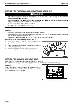
METHOD FOR ADJUSTING OPERATOR'S SEAT
k
k
WARNING
When adjusting the position of the operator's seat, always set the lock lever to LOCK position to pre-
vent any malfunction due to accidental contact with the control levers.
NOTICE
If the seat position is adjusted while the parts, tools, or empty cans are left around the operator's seat,
the peripheral parts or operator's seat may be damaged.
Check that there is no parts etc., around the operator's seat, and adjust the seat position.
OPERATION
MACHINE OPERATIONS AND CONTROLS
3-149
Содержание PC700LC-11
Страница 2: ......
Страница 23: ...LOCATION OF SAFETY LABELS 5 SAFETY SAFETY LABELS 2 3...
Страница 66: ......
Страница 67: ...OPERATION Please read and make sure that you understand the SAFETY section before reading this section 3 1...
Страница 73: ...REMARK The above figure does not show all of the caution lamp symbols OPERATION GENERAL VIEW 3 7...
Страница 316: ......
Страница 317: ...MAINTENANCE Please read and make sure that you understand the SAFETY section before reading this section 4 1...
Страница 331: ...Fuel main fil ter cartridge Replace Replace Replace Replace MAINTENANCE MAINTENANCE SCHEDULE 4 15...
Страница 375: ...A Important inspection part F Front Revolving frame Center frame MAINTENANCE MAINTENANCE PROCEDURE 4 59...
Страница 396: ......
Страница 397: ...SPECIFICATIONS 5 1...
Страница 401: ...For 7 6m Boom SPECIFICATIONS SPECIFICATIONS 5 5...
Страница 402: ...SPECIFICATIONS SPECIFICATIONS 5 6...
Страница 426: ......
Страница 427: ...REPLACEMENT PARTS 7 1...
Страница 434: ......
Страница 442: ...PC700LC 11 HYDRAULIC EXCAVATOR Form No UENAM01321 2017 KOMATSU All Rights Reserved Printed in Belgium 09 2017...


